NDI GO Decoder
1. Product Overview
Section titled “1. Product Overview”1.1 Introduction
Section titled “1.1 Introduction”Welcome to the CND Live NDI GO Decoder. As a specialized manufacturer in the IP video sector, CND Live is dedicated to providing high-quality and reliable equipment.
The NDI GO is a compact, cost-effective professional device designed for 4K video production and display scenarios. It balances portability with powerful decoding capabilities, allowing you to receive video over a network and output it to standard HDMI displays with ultra-low latency.
1.2 Key Features
Section titled “1.2 Key Features”- Full Protocol Support: Fully compatible with NDI High Bandwidth, NDI|HX2, and NDI|HX3.
- 4K UHD Output: Supports decoding up to 4Kp60 resolution via HDMI.
- Plug-and-Play: Integrated PoE (Power over Ethernet) allows power and data transmission over a single cable.
- Intercom Support: Front USB port supports headsets for voice intercom with the CND Live Manager platform.
- Peripheral Control: Supports USB numeric keypads for physical channel switching.
1.3 Technical Specifications
Section titled “1.3 Technical Specifications”| Feature | Specification |
|---|---|
| Video Output | 1x HDMI 2.0 (Up to 3840x2160p 60Hz) |
| Network | 1x Gigabit Ethernet (1000M) with PoE Support |
| Audio Interface | 1x 3.5mm Line Out (Analog Stereo) |
| USB Interface | 1x USB 3.0 (Type-A), 1x USB Type-C |
| Power Input | DC 12V/2A or PoE (802.3af) |
| Audio Decoding | Up to 8 Channels |
| Working Temp | -10℃ ~ 45℃ |
2. Hardware Interfaces
Section titled “2. Hardware Interfaces”2.1 Interface Diagram
Section titled “2.1 Interface Diagram”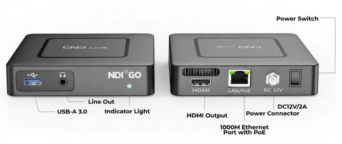
Front Panel
- USB 3.0 (Type-A): Connect a USB headset (for intercom) or a USB Numeric Keypad (for channel switching).
- Line Out: 3.5mm analog audio jack. Connect headphones or speakers to monitor audio.
- Status Indicator: LED light indicating power and network connection status.
Rear Panel
- HDMI OUT: Connect to a TV, Monitor, or Projector.
- LAN / PoE: Gigabit Ethernet port. Connect to your network switch here.
- DC 12V: Input for the power adapter (optional if using PoE).
- Power Switch: Toggle to turn the device On/Off.
- Reset (Bottom): Pinhole button. Press and hold for 5 seconds to restore factory settings.
3. Installation & Connection
Section titled “3. Installation & Connection”Because the NDI Go is a dedicated endpoint device, its physical deployment is incredibly simple and fast.
3.1 Power Supply
Section titled “3.1 Power Supply”You have two options to power the device:
- PoE (Recommended): Connect an Ethernet cable from a PoE-enabled Network Switch to the LAN port. No power brick is needed. This is the cleanest setup for mounting behind TVs.
- DC Adapter: If your switch does not support PoE, connect the provided 12V DC power adapter.
3.2 Video Output Connection
Section titled “3.2 Video Output Connection”- Connect a high-quality HDMI cable from the HDMI OUT port on the NDI Go to your display (TV, Projector, or Broadcast Monitor).
3.3 Network Connection
Section titled “3.3 Network Connection”- Connect the NDI Go to your Local Area Network (LAN) using a Gigabit (1000Mbps) Ethernet cable.
- The device is configured to use DHCP by default, meaning it will automatically request an IP address from your network router the moment it is plugged in.
3. Web Management (Configuration)
Section titled “3. Web Management (Configuration)”The Web UI is the central command station for your NDI Go. Here, you will discover network streams, configure decoding parameters, and assign your quick-switch presets.
3.1 Login Methods & IP Addressing
Section titled “3.1 Login Methods & IP Addressing”The NDI Go features an intelligent network detection system. By default, it uses DHCP to obtain an IP address from your network router.
The Fallback Mechanism: If the NDI Go fails to detect a DHCP server upon booting (for example, if you connect it directly to a laptop without a router), it will automatically assign itself a fallback static IP address: 192.168.1.10.
Choose the login method that matches your current network environment:
Scenario A: Network WITH a DHCP Server (Standard Router/Switch)
Section titled “Scenario A: Network WITH a DHCP Server (Standard Router/Switch)”Method 1: SSDP (Windows Network Discovery) — 🏆 Recommended
Because the NDI Go actively broadcasts its identity over the local network via SSDP (Simple Service Discovery Protocol), you do not need to know its dynamic IP address to find it.
- Open Windows File Explorer on a PC connected to the same network.
- Click on Network in the left sidebar.
- Look under the “Other Devices” section for an icon named
NDIGo-XXXX(where XXXX is the device’s serial number). - Double-click the icon. Your default web browser will automatically open the device’s login page.
Method 2: NDI Studio Monitor
- Open the free NDI Studio Monitor application.
- Open the source menu to view available devices.
- Locate the NDI Go device and click the Gear Icon (⚙️) in the bottom right corner of the screen to jump to its Web UI.
Notice: Because the NDI Go is a dedicated decoder, displaying it in the NDI “Source” list can sometimes clutter the interface for technical directors trying to find actual camera feeds. In future firmware updates, its NDI broadcast beacon may be disabled by default. Therefore, we highly recommend adopting the SSDP method (Method 1) as your standard workflow.
Scenario B: Network WITHOUT a DHCP Server (Direct PC Connection)
Section titled “Scenario B: Network WITHOUT a DHCP Server (Direct PC Connection)”Use this method if you are in the field without a router, or if you are configuring the device for the first time by plugging it directly into your computer.
- Connect an Ethernet cable directly from your computer to the NDI Go’s LAN port.
- Power on the NDI Go. Wait a few seconds for the fallback IP to activate.
- Configure your computer’s network adapter to use a static IP in the same subnet:
- IP Address:
192.168.1.20(or any available IP ending between 2-254, except 10) - Subnet Mask:
255.255.255.0
- IP Address:
- Open your web browser and type the fallback address:
http://192.168.1.10
3.2 Login Credentials
Section titled “3.2 Login Credentials”Once the Web UI loads, enter the default credentials to access the dashboard:
- Username:
admin - Password:
admin
3.3 Dashboard & Preview
Section titled “3.3 Dashboard & Preview”Because the NDI Go is a dedicated decoder, its main dashboard focuses entirely on monitoring and routing incoming streams. There are no encoding settings to configure, making the interface incredibly fast and intuitive.
1. Decoding Preview & PTZ Control
The top section of the dashboard is your primary monitoring window. Before routing a stream to your physical TV or monitor, you can preview it directly within your web browser.
- Video Stream vs. Image Stream: * Select Video Stream for a full-motion, real-time preview of the decoded source.
- Select Image Stream if you are accessing the UI remotely over a slow VPN or through a strict firewall. This failsafe mode refreshes a static frame every 3 seconds, ensuring you always have visual confirmation of your signal without consuming massive bandwidth.
- PTZ Control (Pan-Tilt-Zoom): If the NDI source you are decoding is a PTZ camera, click the PTZ Icon in the preview window. The on-screen controller allows you to manipulate the camera’s movement, adjust focus, and instantly recall up to 255 camera presets without needing an external joystick.
By using the NDI Go’s built-in PTZ panel, you can instantly control any remote NDI camera on your network without needing to log into the camera’s separate web interface or purchase an expensive hardware joystick console!
3.4 Discovering & Routing Sources
Section titled “3.4 Discovering & Routing Sources”The NDI Go automatically scans your network and populates a unified list of all active NDI sources.
How to Switch Channels
In the source list on the left, you have two primary ways to push a stream to your HDMI display:
<↑>Direct Decode Icon : Instantly pulls the selected NDI/OMT stream and routes it directly to your display.+Preset Assignment Icon : Opens a sub-menu allowing you to assign this source to one of the 9 Preset Slots. By mapping your most frequently used cameras to these slots, you effectively turn the NDI Go into a rapid-switching video hub.
3.5 Output Settings & Audio Matrix
Section titled “3.5 Output Settings & Audio Matrix”The right side of the dashboard manages how the decoded stream is processed before it leaves the HDMI port. While pulling a video stream is straightforward, professional broadcast environments demand precise control over how that signal is formatted and routed physically.
To the right of the Decoding Configuration panel, locate the Channels setting. Next to it, you will see a Mixer Icon (visualized as equalizer sliders). Clicking this icon unlocks the NDI Go’s built-in Audio Matrix.
Understanding the Audio Matrix
Standard NDI streams can carry up to 8 independent channels of uncompressed digital audio. The Audio Matrix acts as an internal hardware cross-point switcher, allowing you to extract specific audio tracks from the IP stream and send them exclusively to your desired physical outputs (HDMI or the 3.5mm Analog Line Out).
Decoding (Left): Monitors the real-time audio volume levels of the incoming IP stream tracks (CH 1 through CH 8).
Source (Right): Represents the dropdown selectors where you map specific incoming audio channels to the corresponding output paths.
3.6 Network Configuration
Section titled “3.6 Network Configuration”Unlike dual-LAN devices, the NDI Go features a highly streamlined network architecture with a single Gigabit Ethernet (LAN) port. This port supports PoE (Power over Ethernet), allowing the device to draw power and receive heavy video data simultaneously through one single cable.
Wired Network (LAN) Settings
This section defines how the NDI Go identifies itself on your local network.
- DHCP (Default): When toggled ON, the NDI Go will automatically request an IP address, Subnet Mask, and Gateway from your network router. The input fields will be greyed out, displaying the automatically assigned values.
- Static IP: For permanent installations, toggle DHCP OFF. The input fields will unlock, allowing you to manually type in a specific
IP Address,Gateway,Subnet Mask, andDNS.
SNMP (Simple Network Management Protocol)
For large-scale deployments (such as digital signage across a university campus or a massive multi-view wall in a broadcast center), managing dozens of decoders individually via their Web UIs is inefficient.
The NDI Go supports SNMP, allowing centralized Network Management Systems (NMS like Zabbix, PRTG, or SolarWinds) to automatically poll the device for health status and uptime.
- Enable SNMP: Toggle this ON to allow remote monitoring software to query the device.
- Port: The standard SNMP communication port is 161. Only change this if your IT administrator specifically requires a custom port for security policies.
- Community: The default read-only community string is
public. You can customize this string to restrict which management servers are allowed to monitor the NDI Go.
While DHCP is incredibly convenient for quick setups, Static IPs are the gold standard for permanent AV installations.
If your facility experiences a power outage and the router reboots, DHCP might assign a completely new IP address to your NDI Go. If you are using central control systems (like Crestron, Bitfocus Companion, or the CNDLive Manager) to remotely control the decoder’s PTZ functions or switch presets, a changed IP address will break that connection. Always assign a Static IP for mission-critical endpoints!
3.7 Settings
Section titled “3.7 Settings”The Settings menu allows you to manage system-level configurations, including user accounts, time synchronization, security, and logs. Most importantly, it is the control center for connecting to the CNDLive Manager platform and configuring the Voice Intercom system.
3.7.1 CNDLive Manager Connection
Section titled “3.7.1 CNDLive Manager Connection”Configure the connection to the centralized management platform for remote control and monitoring.
- Configuration Switch: Toggle ON to enable the connection agent.
- Server Address: Enter the IP address or Domain Name of your CNDLive Manager server (e.g.,
192.168.0.118). - Port: Default communication port is 50000.
- Links: Select which network interfaces to use for the management connection (e.g., LAN1, LAN2).
- Note: You must select at least one active link.
- Connection Status:
- Connected: A green checkbox appears at the top left when the link is established.
- Speed Rate: A real-time graph at the bottom displays the bandwidth usage (Kb/s) specifically for the management connection, helping you diagnose network stability.
3.7.2 Voice Intercom
Section titled “3.7.2 Voice Intercom”The Intercom feature enables real-time voice communication between the device operator and the studio/director center.
Status Indicators
The main dashboard provides instant status feedback:Intercom Group
- Not Joined (Grey): Device is disconnected from the intercom group.
- Joined (Green): Device is successfully connected and ready to go.
Headset
- Unplugged (Grey): No audio device detected.
- Plugged (Green): A USB headset/microphone is correctly recognized.
Intercom Settings
Click the Gear Icon next to the intercom status to fine-tune audio performance:- Voice Input: Select your specific USB audio device from the dropdown list (e.g., “Lenovo Services E01”).
- Mic Level: Adjust the microphone gain (Input volume).
- Output Level: Adjust the headphone volume (Monitoring volume).
- Audio Quality: Select the transmission bitrate profile:
- High: Best quality, requires stable bandwidth.
- Middle: Balanced option (Recommended).
- Low: Lowest bandwidth usage, suitable for poor network conditions.
3.7.3 User Management
Section titled “3.7.3 User Management”This section allows you to manage access credentials for the device. You can create multiple user accounts to secure the device settings.
Adding a User
To create a new account, follow these steps:- Click the + Add User button at the top right corner.
- In the pop-up window, fill in the required fields:
- User Name: The login ID for the new user.
- Remark: A label or description (e.g., “Staff”, “IT”).
- Password: Set a secure login password.
- Click Apply to save the new user.
Managing Users
The User List displays all current accounts. You can perform the following actions:- Edit: Click the Gear Icon to modify the user’s remark or reset their password.
- Delete: Click the Trash Icon to remove a user account permanently.
- Note: The default admin account cannot be deleted, only edited.
3.7.4 Time and Zone
Section titled “3.7.4 Time and Zone”Ensuring the device runs on the correct time is essential for accurate log recording, troubleshooting, and task scheduling.
Time Configuration
Select one of the three available Modes to synchronize the system clock:- Timing with current PC: Instantly syncs the device’s time with the computer you are currently using to access the Web UI. This is the quickest method for initial setup.
- Manual Timing: Allows you to manually input a specific date and time string (Format:
YYYY-MM-DD HH:MM:SS). This is useful for isolated networks without internet access. - Sync from NTP Server: Connects to a Network Time Protocol server for high-precision, automatic synchronization.
- Setting: You must enter a valid NTP Server Address (e.g.,
pool.ntp.org). Supports multiple addresses separated by spaces.
- Setting: You must enter a valid NTP Server Address (e.g.,
Zone Configuration
Define the geographical region to ensure the offset from UTC is correct.- Region and Position: Click the dropdown menu to select your time zone. The list supports selection by:
- Major Cities: e.g., “Asia/Shanghai”, “Seoul”, “New York”.
- GMT Offsets: e.g., “GMT-8”, “GMT+1”.
3.7.5 System
Section titled “3.7.5 System”The System panel is the hub for device maintenance. Here you can view hardware details, perform firmware upgrades, reset configurations, or restart the device.
Device Info
Displays critical identity information for the device:- Versions: View current Hardware and Software versions to determine if an update is needed.
- Serial Number: Click the ❐ to quickly copy the SN to your clipboard (Essential information for connecting to CNDLive Manager and technical support).
- Device Name: Click the ✏️ to rename the device. This name identifies the unit on the network and in the NDI discovery list.
SSDP (Simple Service Discovery Protocol)
When deploying multiple decoders across a large Local Area Network (LAN), manually tracking IP addresses can become a headache.- SSDP Toggle: By turning this ON, the A1 Decoder actively broadcasts its digital signature across the local network. This allows standard operating systems (like Windows Network Explorer) and CNDLive central management software to automatically “discover” the device without needing its exact IP address.
- Recommendation: Leave this enabled for convenient plug-and-play management, unless your facility’s strict IT security policies prohibit local network multicasting.
Firmware Update
Keep your device running efficiently by installing the latest software.- Select File: Click to browse your local computer for the update file.
- Requirement: The file must be in .bin format.
- Update: Once the filename appears, click the Update button to begin.
- Warning: Do not disconnect power during the update process to prevent system corruption.
Reset Factory Settings
This operation restores the device to its original out-of-the-box state.- Action: Click Reset to wipe all custom configurations (Network IP, Encoding params, User accounts, etc.).
- Result: The device will revert to default settings and automatically reboot.
Reboot
Performs a safe software restart of the device.- Action: Click Reboot to restart the system without losing your saved configurations.
- Duration: The process typically takes about 30 seconds.
3.7.6 Security
Section titled “3.7.6 Security”The Security settings allow you to configure the network protocols used to access the device’s Web User Interface, ensuring secure data transmission.
HTTP/HTTPS Setting
Configure the ports and protocols for web access:- HTTP: Standard web traffic.
- Checkbox: Check to enable HTTP access (Default: Enabled).
- Port: Default is 80. You can customize this if port 80 is blocked or used by other services.
- HTTPS: Encrypted web traffic (Recommended for public network access).
- Checkbox: Check to enable HTTPS access.
- Port: Default is 443.
Certificate Management
To use HTTPS securely without browser warnings, you must upload valid SSL certificates.- CA Certificate: Drag and drop your certificate file here.
- Format Requirement: Supports .crt files.
- CA Secret Key: Drag and drop the corresponding private key file here.
- Format Requirement: Supports .key files.
3.8.8 NDI Discovery Server
Section titled “3.8.8 NDI Discovery Server”By default, the NDI Go uses mDNS (Multicast) to automatically discover video sources on the same local subnet. However, if your video sources (encoders, PTZ cameras, vMix servers) are located on a different subnet or VLAN, the mDNS broadcast will be blocked by your network router. This is where the Discovery Server comes in.
If you are pulling NDI streams across a complex corporate network:
- Enable: Toggle this switch ON. This tells the NDI Go to stop relying on local multicast and instead ask a central server for the stream directory.
- Server IP: Enter the exact IP address of the machine running the NDI Access Manager (the central registry). Once connected, the NDI Go will instantly display all NDI sources registered to that server, regardless of physical network boundaries.
4. Troubleshooting & FAQ
Section titled “4. Troubleshooting & FAQ”Even in the most meticulously planned live productions, network environments can be unpredictable. This section is designed to help you quickly diagnose and resolve the most common decoding and network issues encountered in the field.
Q1: I plugged in the NDI Go, but I don’t know its IP address.
A: Because the NDI Go has no LCD screen, it relies on intelligent network discovery.
- If you have a Router (DHCP): Open Windows File Explorer, click Network, and look for
NDIGo-XXXXunder “Other Devices” (SSDP method). Double-click it to enter the Web UI.- If you don’t have a Router: Connect the device directly to your PC. The NDI Go will automatically assign itself a fallback IP. Set your PC’s IP to
192.168.1.20, open your browser, and go tohttp://192.168.1.10.
Q2: The video output on my TV is stuttering, freezing, or dropping frames.
A: Video stuttering on a decoder is almost always caused by network bandwidth limitations or packet jitter, especially when pulling Full NDI (NDI|HB) streams.
- Check your switch: NDI|HB requires massive bandwidth (up to 250 Mbps for 4K). Ensure your entire network infrastructure (switches and cables) is rated for Gigabit (1000M). A 100M switch will instantly choke.
- Increase the Network Buffer: Go to the Decoding Settings panel and increase the Network Buffer (Jitter Control) from its default to 120ms or higher. This adds a tiny fraction of delay but acts as a powerful shock absorber for unstable networks.
Q3: The Web UI video preview only updates once every 3 seconds. Is it broken?
A: No, this is working exactly as designed. You have selected the Image Stream preview. Full-motion web previews require specific network ports to be open. If you are on a strict corporate network, the live video player may be blocked by the firewall. The Image Stream bypasses this by using standard HTTP requests (1 frame / 3 seconds) to ensure you still have visual confirmation of your signal. Your actual physical HDMI output is still running flawlessly at a full 60fps.
Q4: My source list is empty. I cannot see the NDI cameras from the main studio.
A: By default, NDI uses mDNS (multicast) to discover devices, which cannot cross different subnets or VLANs (e.g., the studio is on
192.168.1.xand the NDI Go is on192.168.2.x).
- The Fix: Go to Settings -> Advanced Settings and toggle ON the NDI Discovery Server. Enter the IP address of your central NDI Access Manager. This will instantly bridge the networks and populate your source list.
Q5: The video looks great on the monitor, but there is no audio.
A: Professional NDI streams often carry multiple isolated audio tracks (up to 8 channels), and the NDI Go requires you to specify which tracks to listen to.
- The Fix: On the dashboard, click the Mixer Icon next to the Channels setting to open the Audio Matrix. Ensure that the incoming NDI Audio Channels (e.g., CH 1 and CH 2) are explicitly checked and mapped to HDMI Out L and HDMI Out R.
When a monitor goes black in the field, don’t panic. Follow this 3-step logical flow:
1. Ping the Device: Can you access the NDI Go’s Web UI? If yes, the physical cable and power are fine.
2. Check the Source: Look at the NDI Go’s source list. Is the camera still broadcasting? Is the “Connected” badge green? If it’s disconnected, the issue is on the sending encoder’s side or the network switch.
3. Check the Matrix: If the Web UI says “Connected” but the TV is still black or silent, check your output resolution (is it compatible with the TV?) and your Audio Matrix routing.