A1 NDI Bi-Directional Codec
Welcome to the CND Live A1. The A1 is a professional video gateway that bridges the gap between traditional HDMI equipment and IP-based video networks. Unlike standard converters, the A1 is a Bi-Directional Codec, capable of Encoding (Sending) and Decoding (Receiving) video simultaneously.
1. Product Overview
Section titled “1. Product Overview”1.1 Introduction
Section titled “1.1 Introduction”The A1 is designed for live production, broadcast monitoring, and interactive AV integration. Its standout feature is Bi-Directional Operation: it can transmit your camera feed to the network while simultaneously receiving a return program feed to a local monitor.
1.2 Key Features
Section titled “1.2 Key Features”- Simultaneous Encode & Decode: Process bi-directional video streams up to 1080P @ 60Hz.
- Dual Gigabit LAN: Two independent network ports that can be used simultaneously for flexible network configuration (e.g., separate control and data networks).
- High-Performance Single Mode: Dedicated modes for 4K UHD @ 60Hz Encoding or Decoding.
- Dual Protocol Support: Native support for both NDI|HX 2/3 (High Efficiency) and NDI|HB (High Bandwidth / Full NDI).
- PoE+ Power: LAN 1 supports Power over Ethernet for single-cable operation.
- Intercom & Control: USB interface for voice talkback and PTZ camera control.
1.3 Interface Description
Section titled “1.3 Interface Description”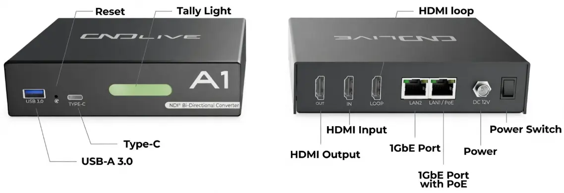
| ID | Component | Function |
|---|---|---|
| 1 | USB 3.0 | Connect USB headset (Intercom) or numeric keypad (Preset switching). |
| 2 | Reset | Factory reset button (Hold for 5 seconds). |
| 3 | Type-C | Auxiliary expansion/debugging port. |
| 4 | Tally Light | Large status indicator (Red=Program/Live, Green=Preview). |
| 5 | HDMI OUT | Connect to a TV/Monitor (Decoding Output). |
| 6 | HDMI IN | Connect Camera/PC (Encoding Input). |
| 7 | HDMI LOOP | Zero-latency local loop-through output for monitoring. |
| 8 | LAN 2 | Static IP Port. Non-PoE. Default IP: 192.168.1.10. Ideal for direct PC configuration or non-DHCP networks. |
| 9 | LAN 1 / PoE | Primary Network Port. Supports PoE. Obtains IP via DHCP automatically (No default static IP). |
| 10 | DC 12V | Power input (required if connecting via LAN 2 or non-PoE switch). |
| 11 | Power Switch | Physical On/Off rocker switch. |
2. Installation & Connection
Section titled “2. Installation & Connection”2.1 Power Supply
Section titled “2.1 Power Supply”You have two options to power the device:
- PoE (LAN 1 Only): Connect an Ethernet cable from a PoE Switch to LAN 1. No power brick is needed.
- DC Adapter: Connect the provided 12V/2A adapter.
2.2 Video Connections
Section titled “2.2 Video Connections”- To Encode (Send): Connect your video source (Camera/Laptop) to HDMI IN.
- (Optional) Connect a local monitor to HDMI LOOP to see the camera shot without delay.
- To Decode (Receive): Connect your display (TV/Projector) to HDMI OUT.
2.3 Network Connection
Section titled “2.3 Network Connection”The A1 features two distinct network ports that can be used simultaneously. Choose the port that fits your setup:
-
LAN 1 (PoE / DHCP):
- Use this for standard network connections with a router/switch.
- Supports PoE power.
- Automatically obtains an IP address (DHCP).
-
LAN 2 (Static / Config):
- Use this for initial configuration without a router, or for a dedicated management network.
- Does not support PoE.
- Fixed Default IP:
192.168.1.10
3. Web Management (Configuration)
Section titled “3. Web Management (Configuration)”3.1 Login Methods
Section titled “3.1 Login Methods”This is the control center for A1.
Method A: Via LAN 1 (Standard DHCP Network)
Section titled “Method A: Via LAN 1 (Standard DHCP Network)”- Connect LAN 1 to your network router.
- On a computer on the same network, open Windows File Explorer -> Network.
- Look under “Other Devices” for
A1-XXXX(where XXXX is the serial number). - Double-click the icon to open the management page.
- Alternatively, use the free NDI Studio Monitor tool, find the source named “A1…”, and click the Gear Icon (⚙️).
Method B: Via LAN 2 (No DHCP / Direct Connection)
Section titled “Method B: Via LAN 2 (No DHCP / Direct Connection)”Use this method if you do not have a router or are configuring the device for the first time offline.
- Connect an Ethernet cable directly from your computer to LAN 2.
- Configure your computer’s network adapter to a static IP in the same range:
- IP Address:
192.168.1.20(or any available IP in the 1.x segment) - Subnet Mask:
255.255.255.0
- IP Address:
- Open a web browser and enter the default address:
Default Credentials:
- Username:
admin - Password:
admin
3.2 Operation Mode (Mode Switch)
Section titled “3.2 Operation Mode (Mode Switch)”The A1 is designed to be the ultimate multi-tool for IP video production. Depending on your on-site requirements, you can allocate the device’s hardware processing power to act as a bi-directional transceiver, a dedicated high-performance encoder, or a dedicated decoder.
1. Protocol Tabs: NDI vs. OMT
At the top right of the Mode Switch window, you can toggle between the NDI and OMT protocol environments. Because these protocols have different compression architectures and hardware demands, the maximum resolution and framerate capacities of the A1 will dynamically update based on the tab you select.
2. Hardware Allocation Modes
Click on one of the three large cards to instantly reconfigure the A1’s operational mode.
- Encoder & Decoder (Bi-Directional)
- Use Case: Perfect for remote interviews, live return feeds (PGM return), or interactive stage setups.
- Capability: The A1 splits its processing core to simultaneously encode an incoming HDMI/SDI video feed while decoding a separate network stream at the same time. In this mode, both the encoder and decoder pipelines are capped at a maximum of 1080P at 60fps to ensure stable dual-way performance.
- Encoder Only (Dedicated)
- Use Case: When you need to push a pristine, ultra-high-definition feed to the network (e.g., transmitting a 4K camera signal to a central production switcher).
- Capability: By disabling the decoding module, 100% of the device’s processing power is dedicated to capturing and encoding. This unlocks the ability to transmit up to 4K at 60fps (via NDI|HX).
- Decoder Only (Dedicated)
- Use Case: Powering a large 4K reference monitor, a digital billboard, or feeding a 4K broadcast matrix.
- Capability: Shuts down the encoding engine, channeling all resources to pull and render heavy incoming IP streams. This unlocks the ability to decode and output up to 4K at 60fps (via NDI|HX or NDI|HB).
Always match the mode to your actual task. If you are only using the A1 to receive a stream for a display monitor, do not leave it in “Encoder & Decoder” mode. Switching it to Decoder Only ensures the device runs cooler, utilizes less CPU, and gives you the overhead needed to handle 4K resolutions flawlessly.
3.3 NDI Encoding Mode
Section titled “3.3 NDI Encoding Mode”The Encoding Mode is the core engine of the A1. When operating in Encoder & Decoder or Encoder Only mode, this section allows you to capture baseband video, configure high-efficiency compression parameters, and push standard NDI streams to your local network.
Preview Window
The Preview Window is your primary confidence monitoring tool, ensuring that your baseband video is successfully entering the A1 and is ready for encoding.
Input Source Toggle: Located at the top of the interface, this toggle allows you to seamlessly switch the encoding target between the physical HDMI port and a connected USB Camera. This is highly useful for quick setups where a USB webcam is used as a secondary angle.
Video Preview: This is the primary, full-motion live preview of your selected input source, rendered in real-time. It also displays the current baseband video format (e.g., 1920x1080P 59.94Hz) overlaying the top left corner of the stream.
Image Preview: To ensure maximum reliability across complex network topologies, the A1 features a secondary monitoring pipeline. This failsafe viewer captures and transmits a static image frame every few seconds.
Stream Encoding Status
Just below the preview window, you will find the Stream Encoding Status dashboard. Because the A1 features native dual-protocol support, this panel provides real-time, side-by-side telemetry for both your NDI|HX (High Efficiency) and NDI|HB (High Bandwidth / Full NDI) encoding pipelines.
This dashboard is your ultimate diagnostic tool for network transmission. Here is what each metric signifies:
- Resolution & Framerate: Displays the final video format currently being pushed to the network. Keep in mind that the A1 has built-in hardware scalers. For example, if your camera inputs 4K, but you only need a 1080P stream, this panel confirms the scaled output dimension.
- Codec: Indicates the compression engine currently in use. NDI|HX typically utilizes high-efficiency H.264 or H.265 (HEVC), whereas NDI|HB utilizes the intra-frame SpeedHQ (SHQ2) algorithm for near-zero latency and visually lossless quality.
- Bitrate: Shows the real-time network bandwidth consumption of the video stream. This value will dynamically fluctuate depending on the complexity of the video scene (e.g., a static interview vs. fast-moving sports).
- Sampling & Channels: Displays the health of the embedded audio matrix. The A1 supports up to 8 channels of uncompressed digital audio synchronization.
NDI Encoding Settings
Scroll down to the Encoding Settings section. This is where you define how your baseband video is compressed, packaged, and identified across your local network.
Because the A1 is a dual-protocol engine, the configuration parameters will dynamically change depending on whether you are adjusting NDI|HX or NDI|HB.
3.1 Common Settings (Applicable to both NDI|HX and NDI|HB)
These settings govern the identity and the audio pipeline of your NDI stream, regardless of the video compression protocol you choose.
- Stream Name (Channel Name): The public identity of your video feed (e.g.,
CAM-1_Wide). This is what appears in the source lists of your NDI receivers. - NDI Group: Assign a custom Group Name (e.g.,
Broadcast_Team) to hide your stream from the general network. Only receivers configured to join this specific group will see the feed. - Audio Settings:
- Audio Channels: Select the number of audio channels to embed in your stream (1, 2, 4, 6, or 8 channels).
- Sample Rate: Adjust the audio sampling frequency (e.g., 48000 Hz) to match your downstream production equipment.
- Volume: Fine-tune the digital gain of the encoded audio to prevent clipping or boost quiet sources.
- Audio Matrix (Mixer Icon): Click the Mixer Icon located to the right of the audio channel settings. This opens a powerful cross-routing matrix, allowing you to manually map specific physical input tracks (e.g., HDMI Audio Ch 3) to specific NDI output tracks (e.g., NDI Stream Ch 1).
NDI|HX Specific Settings (High Efficiency)
NDI|HX utilizes Inter-frame compression, making it highly efficient for standard Gigabit networks or Wi-Fi.
-
NDI Options (Protocol Version):
- NDI|HX2: The highly compatible standard, utilizing H.264/HEVC.
- NDI|HX3: The next-generation protocol. It offers significantly lower latency and better visual quality than HX2, bridging the gap to Full NDI while using a fraction of the bandwidth. (Note: Ensure your receiving software is updated to support HX3).
-
Codec: Choose between H.264 (maximum compatibility with older decoders) and H.265 / HEVC (superior image quality at lower bitrates).
-
Resolution & Framerate: Select
Same as Inputto preserve the original format, or force the A1’s hardware scaler to change the output resolution (e.g., downscaling 4K to 1080p). -
Encoding Bitrate (Kbps): Defines the target data rate. Higher values yield better image quality but demand more network bandwidth.
-
Profile (Quality Target): This parameter dictates the computational effort the encoder puts into video quality.
- The default value is 100.
- You can adjust this from 20 (Lowest Quality / Fastest Processing) up to 400 (Maximum Quality).
-
Audio Encoding Bitrate & LFE: For HX streams, you can define the specific audio compression bitrate. Additionally, you can toggle the LFE (Low-Frequency Effects) switch to preserve dedicated subwoofer channels if you are transmitting surround sound.
3.4 NDI Decoding Mode
Section titled “3.4 NDI Decoding Mode”When the A1 operates in Encoder & Decoder or Decoder Only mode, the Decoding Mode panel becomes your control hub for pulling incoming NDI streams from the network and converting them back to baseband HDMI output.
Decoding Preview & PTZ Control
Before routing a stream to your physical monitors, you can preview and manipulate the incoming source directly within the Web UI. By using the A1’s built-in PTZ panel, you can instantly control any remote NDI camera on your network without needing to log into the camera’s separate web interface or purchase an expensive hardware joystick console!
- Preview Stream Selection:
- Video Stream: Provides a full-motion, real-time preview of the decoded NDI source.
- Image Stream: Similar to the encoding side, this acts as a low-bandwidth failsafe viewer. It refreshes a static frame every few seconds, guaranteeing a visual confidence check even when you are remotely managing the A1 across firewalls or restricted VPNs.
- PTZ Control (Pan-Tilt-Zoom): NDI is a bi-directional protocol. If the NDI source you are decoding is a PTZ camera, clicking the PTZ Icon in the bottom right corner of the preview window will bring up an on-screen controller.
- You can smoothly control the camera’s movement and optical zoom directly from the A1’s web interface without needing a dedicated hardware joystick.
- Preset Management: The PTZ panel allows you to save and instantly recall up to 255 camera presets. This is incredibly useful for solo operators or live events where you need to quickly snap the camera to pre-defined angles (e.g., “Wide Stage,” “Podium,” or “Guest 1”).
Decoding Source Status
Once you have selected an NDI source to decode, the Status Dashboard located just below the preview window provides instant, real-time telemetry on the health of your connection.
Understanding these states will help you quickly diagnose signal issues in the field:
- Connected: The ideal state. The A1 has successfully locked onto the NDI stream, handshakes are complete, and the hardware is actively decoding the video frames. The panel will display the incoming baseband resolution and the protocol type (HX or HB).
- Disconnected: The A1 recognizes the source name in the NDI registry, but cannot pull the actual video data.
- Common Causes: The source device was powered off, the network cable was unplugged, or a strict firewall rule is blocking the video data packets between subnets.
- Unsupported / Exceeds Capability : The stream is active and reachable, but the A1 refuses to decode it because the incoming video format exceeds the currently allocated hardware limits.
Adding & Managing NDI Sources
The A1 automatically scans your Local Area Network (LAN) and populates a list of all active NDI sources. In the Edit column next to each discovered source, you will find two primary action buttons that dictate how the stream is handled.
<↑>Direct Decode Icon: Clicking the Up-Arrow icon instructs the A1 to immediately pull this specific NDI stream and route it directly to the HDMI output. This is the fastest way to get a single video source up on your screen.+Preset Assignment Icon: Clicking the Plus icon opens a sub-menu that allows you to assign this NDI source to one of the 9 Preset Slots.
4. Advanced Decoding Settings & Audio Matrix
While pulling a video stream is straightforward, professional broadcast environments demand precise control over how that signal is formatted and routed physically.
To the right of the Decoding Configuration panel, locate the Channels setting. Next to it, you will see a Mixer Icon (visualized as equalizer sliders). Clicking this icon unlocks the A1’s built-in Audio Matrix.
Understanding the Audio Matrix
Standard NDI streams can carry up to 8 independent channels of uncompressed digital audio. The Audio Matrix acts as an internal hardware cross-point switcher, allowing you to extract specific audio tracks from the IP stream and send them exclusively to your desired physical outputs (HDMI or the 3.5mm Analog Line Out).
Decoding (Left): Monitors the real-time audio volume levels of the incoming IP stream tracks (CH 1 through CH 8).
Source (Right): Represents the dropdown selectors where you map specific incoming audio channels to the corresponding output paths.
3.5 OMT Encoding Mode
Section titled “3.5 OMT Encoding Mode”OMT (Open Media Transport) is a next-generation, high-performance protocol designed for ultra-low latency video transmission over a Local Area Network (LAN). It serves as an open-standard alternative to proprietary formats like NDI.
If you are already familiar with configuring NDI on the A1, you will feel right at home here. The OMT encoding architecture shares a nearly identical user interface and operational logic with the NDI|HX engine.
Stream Preview & Telemetry
The top half of the OMT Encoding dashboard mirrors the NDI layout exactly:
- Dual-Pipeline Preview: You have access to the same Real-Time Video Stream for full-motion monitoring and the Failsafe Image Stream (1 frame / 3 seconds) for penetrating strict firewalls and port forwarding setups.
- Telemetry Dashboard: Provides real-time readouts of your scaled Output Resolution, Framerate, active Codec (H.264/H.265), dynamic Bitrate, and Audio Channels.
OMT Encoding Settings
Scroll down to configure the network payload. The parameters here follow the same rules as NDI:
- Stream Name & Group: Define the public identity of your OMT feed (e.g.,
CAM-2_OMT) and assign it to a specific network group if you want to isolate the traffic from general receivers. - Video Scaling: Force a specific resolution and framerate to save bandwidth, or leave it as
Same as Input.
3.6 OMT Decoding Mode
Section titled “3.6 OMT Decoding Mode”Just as with the encoding side, the OMT Decoding Mode shares its operational DNA with the NDI decoding interface. If you have mastered pulling and routing NDI streams on the A1, you are already fully equipped to handle OMT streams.
OMT Source Discovery & Playback
The A1 continuously listens across your Local Area Network (LAN) for active OMT senders (such as an OBS Studio instance equipped with an OMT plugin, or another CNDLive device).
- Direct Decode (
<↑>Icon): Click the green arrow to immediately decode the selected OMT stream and send it to your physical HDMI output. - Preset Assignment (
+Icon): Click the blue plus icon to assign the OMT source to one of your 9 Quick-Switch preset slots, allowing for instant camera cutting during a live event.
Decoding Parameters & Routing
Once an OMT stream is active, you have full access to the same robust output controls as NDI:
- Hardware Scaler: Force the decoded OMT stream to a specific resolution (e.g., scale a 4K stream down to 1080p for an older monitor).
- Audio Matrix: Click the Mixer icon to map specific incoming OMT digital audio channels to your physical HDMI or analog Line-Out ports.
3.7 Network Settings
Section titled “3.7 Network Settings”Stable network connectivity is the absolute foundation of any IP decoding workflow. The A1 Decoder is equipped with a professional Dual Gigabit Ethernet architecture, allowing you to physically separate your management network from your high-bandwidth streaming network.
3.7.1 Wired Network 1
Section titled “3.7.1 Wired Network 1”Ethernet 1 is the primary data port. It supports PoE (Power over Ethernet), meaning you can power the A1 and deliver data using a single cable connected to a PoE-enabled switch.
By default, Ethernet 1 is configured to seamlessly integrate into most standard network environments:
- DHCP Toggle: When turned ON (default), the decoder will automatically request an IP address, Gateway, and DNS from your router. This is the recommended setting for plug-and-play operation.
- Static IP Configuration: If your facility requires fixed IP addresses, turn DHCP OFF and manually input your
IP Address,Gateway,Netmask, andDNSservers. - Status Information: Check the
Statustext (ConnectedorUnlink) to verify the physical cable connection. TheMAC Addressis also displayed here, which is useful if your IT department requires MAC address whitelisting.
3.7.2 Wired Network 2
Section titled “3.7.2 Wired Network 2”Ethernet 2 serves as a secondary data pipeline or a dedicated management port.
Unlike Ethernet 1, this port is pre-configured with a static IP address to ensure you never lose access to the device, even if your main router fails.
- Default Static IP: By default, DHCP is toggled OFF, and the interface is assigned a static IP of
192.168.1.10. - Direct Laptop Connection: If you are in the field without a router and need to configure the A1, you can plug an Ethernet cable directly from your laptop to Ethernet 2. Simply set your laptop’s IP address to the same subnet (e.g.,
192.168.1.100), open your browser, and type192.168.1.10to access the Web UI.
3.7.3 SNMP
Section titled “3.7.3 SNMP”For large-scale deployments, managing individual Web UIs for dozens of decoders is inefficient. The A1 supports SNMP (Simple Network Management Protocol), allowing centralized Network Management Systems (NMS like Zabbix or PRTG) to poll the device’s health.
- SNMP Toggle: Turn this ON to allow remote monitoring software to query the device.
- Port: The standard SNMP port is 161. Only change this if your IT administrator specifically requires a custom port for security policies.
- Community: The default read-only community string is
public. You can customize this string to restrict which servers are allowed to monitor the A1.
3.8 Settings
Section titled “3.8 Settings”The Settings menu allows you to manage system-level configurations, including user accounts, time synchronization, security, and logs. Most importantly, it is the control center for connecting to the CNDLive Manager platform and configuring the Voice Intercom system.
3.8.1 CNDLive Manager Connection
Section titled “3.8.1 CNDLive Manager Connection”Configure the connection to the centralized management platform for remote control and monitoring.
- Configuration Switch: Toggle ON to enable the connection agent.
- Server Address: Enter the IP address or Domain Name of your CNDLive Manager server (e.g.,
192.168.0.118). - Port: Default communication port is 50000.
- Links: Select which network interfaces to use for the management connection (e.g., LAN1, LAN2).
- Note: You must select at least one active link.
- Connection Status:
- Connected: A green checkbox appears at the top left when the link is established.
- Speed Rate: A real-time graph at the bottom displays the bandwidth usage (Kb/s) specifically for the management connection, helping you diagnose network stability.
3.8.2 Voice Intercom
Section titled “3.8.2 Voice Intercom”The Intercom feature enables real-time voice communication between the device operator and the studio/director center.
Status Indicators
The main dashboard provides instant status feedback:Intercom Group
- Not Joined (Grey): Device is disconnected from the intercom group.
- Joined (Green): Device is successfully connected and ready to go.
Headset
- Unplugged (Grey): No audio device detected.
- Plugged (Green): A USB headset/microphone is correctly recognized.
Intercom Settings
Click the Gear Icon next to the intercom status to fine-tune audio performance:- Voice Input: Select your specific USB audio device from the dropdown list (e.g., “Lenovo Services E01”).
- Mic Level: Adjust the microphone gain (Input volume).
- Output Level: Adjust the headphone volume (Monitoring volume).
- Audio Quality: Select the transmission bitrate profile:
- High: Best quality, requires stable bandwidth.
- Middle: Balanced option (Recommended).
- Low: Lowest bandwidth usage, suitable for poor network conditions.
3.8.3 User Management
Section titled “3.8.3 User Management”This section allows you to manage access credentials for the device. You can create multiple user accounts to secure the device settings.
Adding a User
To create a new account, follow these steps:- Click the + Add User button at the top right corner.
- In the pop-up window, fill in the required fields:
- User Name: The login ID for the new user.
- Remark: A label or description (e.g., “Staff”, “IT”).
- Password: Set a secure login password.
- Click Apply to save the new user.
Managing Users
The User List displays all current accounts. You can perform the following actions:- Edit: Click the Gear Icon to modify the user’s remark or reset their password.
- Delete: Click the Trash Icon to remove a user account permanently.
- Note: The default admin account cannot be deleted, only edited.
3.8.4 Time and Zone
Section titled “3.8.4 Time and Zone”Ensuring the device runs on the correct time is essential for accurate log recording, troubleshooting, and task scheduling.
Time Configuration
Select one of the three available Modes to synchronize the system clock:- Timing with current PC: Instantly syncs the device’s time with the computer you are currently using to access the Web UI. This is the quickest method for initial setup.
- Manual Timing: Allows you to manually input a specific date and time string (Format:
YYYY-MM-DD HH:MM:SS). This is useful for isolated networks without internet access. - Sync from NTP Server: Connects to a Network Time Protocol server for high-precision, automatic synchronization.
- Setting: You must enter a valid NTP Server Address (e.g.,
pool.ntp.org). Supports multiple addresses separated by spaces.
- Setting: You must enter a valid NTP Server Address (e.g.,
Zone Configuration
Define the geographical region to ensure the offset from UTC is correct.- Region and Position: Click the dropdown menu to select your time zone. The list supports selection by:
- Major Cities: e.g., “Asia/Shanghai”, “Seoul”, “New York”.
- GMT Offsets: e.g., “GMT-8”, “GMT+1”.
3.8.5 System
Section titled “3.8.5 System”The System panel is the hub for device maintenance. Here you can view hardware details, perform firmware upgrades, reset configurations, or restart the device.
Device Info
Displays critical identity information for the device:- Versions: View current Hardware and Software versions to determine if an update is needed.
- Serial Number: Click the ❐ to quickly copy the SN to your clipboard (Essential information for connecting to CNDLive Manager and technical support).
- Device Name: Click the ✏️ to rename the device. This name identifies the unit on the network and in the NDI discovery list.
SSDP (Simple Service Discovery Protocol)
When deploying multiple decoders across a large Local Area Network (LAN), manually tracking IP addresses can become a headache.- SSDP Toggle: By turning this ON, the A1 Decoder actively broadcasts its digital signature across the local network. This allows standard operating systems (like Windows Network Explorer) and CNDLive central management software to automatically “discover” the device without needing its exact IP address.
- Recommendation: Leave this enabled for convenient plug-and-play management, unless your facility’s strict IT security policies prohibit local network multicasting.
Firmware Update
Keep your device running efficiently by installing the latest software.- Select File: Click to browse your local computer for the update file.
- Requirement: The file must be in .bin format.
- Update: Once the filename appears, click the Update button to begin.
- Warning: Do not disconnect power during the update process to prevent system corruption.
Reset Factory Settings
This operation restores the device to its original out-of-the-box state.- Action: Click Reset to wipe all custom configurations (Network IP, Encoding params, User accounts, etc.).
- Result: The device will revert to default settings and automatically reboot.
Reboot
Performs a safe software restart of the device.- Action: Click Reboot to restart the system without losing your saved configurations.
- Duration: The process typically takes about 30 seconds.
3.8.6 Security
Section titled “3.8.6 Security”The Security settings allow you to configure the network protocols used to access the device’s Web User Interface, ensuring secure data transmission.
HTTP/HTTPS Setting
Configure the ports and protocols for web access:- HTTP: Standard web traffic.
- Checkbox: Check to enable HTTP access (Default: Enabled).
- Port: Default is 80. You can customize this if port 80 is blocked or used by other services.
- HTTPS: Encrypted web traffic (Recommended for public network access).
- Checkbox: Check to enable HTTPS access.
- Port: Default is 443.
Certificate Management
To use HTTPS securely without browser warnings, you must upload valid SSL certificates.- CA Certificate: Drag and drop your certificate file here.
- Format Requirement: Supports .crt files.
- CA Secret Key: Drag and drop the corresponding private key file here.
- Format Requirement: Supports .key files.
3.8.7 Advanced Settings
Section titled “3.8.7 Advanced Settings”The Advanced Settings menu dynamically adapts its parameters based on the core protocol environment you selected in the Mode Switch panel (NDI or OMT). This section is primarily dedicated to configuring Cross-Subnet Discovery and WAN Transmission, which are essential when deploying the A1 in complex corporate networks or across the internet.
When in OMT Mode
If your A1 is configured to use the OMT protocol, the advanced settings will display the OMT Discovery Server options.
- Default Behavior: OMT typically relies on local network multicast to broadcast its presence.
- OMT Discovery Server: When toggled ON, the A1 stops relying on standard multicast and instead registers itself directly to a centralized OMT registry server via Unicast.
- Server IP: Enter the IP address of the machine hosting the central OMT Discovery service. This allows OMT receivers on completely different subnets to find and pull your stream.
When in NDI Mode
If your A1 is running the NDI|HX or NDI|HB engine, the menu switches to display official NDI tools: NDI Discovery Server and NDI Bridge.
- NDI Discovery Server (Cross-Subnet): Toggling this ON disables the default mDNS broadcast and forces the A1 to announce itself to a specific IP address via Unicast. Enter the IP address of the computer running the NDI Access Manager. This allows devices across different VLANs within your corporate network to see each other.
- NDI Bridge (Cross-Internet): This is a powerful feature for Remote Production (REMI). NDI Bridge allows you to securely share NDI sources between entirely different geographical locations over the public internet (WAN).
- Host IP: Enter the Public IP address of your remote studio’s NDI Bridge Host.
- Port: The specific port opened for the Bridge connection (e.g., 5990).
- Note: Once joined, the A1 acts as a Bridge Node, seamlessly pulling or pushing streams as if the remote studio were on the same local switch.
4. Troubleshooting & FAQ
Section titled “4. Troubleshooting & FAQ”Even in the most meticulously planned live productions, network environments can be unpredictable. This section is designed to help you quickly diagnose and resolve the most common issues encountered in the field.
Q1: I cannot access the Web UI or find the A1 on my network.
A: The A1 features a Dual-LAN architecture. Your troubleshooting steps depend on which port you are using:
- If using LAN 1 (PoE): This port uses DHCP. Ensure your router is assigning IP addresses. Use the NDI Studio Monitor tool on your PC to scan the network for “A1_XXXXX” and click the gear icon to access the UI.
- If connected directly to a PC (No Router): Unplug from LAN 1 and connect your PC directly to LAN 2. Set your PC’s network adapter to a static IP (e.g.,
192.168.1.20) and enter the A1’s default fallback IPhttp://192.168.1.10in your browser.
Q2: The decoding status shows “Unsupported” and I have no video output.
A: This means the incoming NDI stream exceeds the A1’s currently allocated hardware processing limits.
- The Cause: You are likely trying to decode a 4K stream while the A1 is set to Encoder & Decoder (Bi-Directional) mode, which caps both pipelines at 1080P 60Hz.
- The Fix: Go to the Mode Switch tab on the dashboard and click Decoder Only. The device will reboot, freeing up 100% of its processing power to smoothly decode your 4K stream.
Q3: My NDI stream is stuttering, freezing, or dropping frames.
A: Video stuttering is almost always a network bandwidth or jitter issue, especially when using Full NDI (NDI|HB).
- Check your switch: NDI|HB requires massive bandwidth (150-250 Mbps per stream). Ensure your entire network infrastructure (switches and cables) is rated for Gigabit (1000M). A 100M switch will instantly choke.
Q4: The Web UI video preview only updates once every 3 seconds. Is it broken?
A: No, this is working by design. You are likely looking at the Failsafe Image Stream. Full-motion web previews require specific network ports to be open. If you are on a strict corporate network or accessing the A1 remotely via port forwarding, the live video player may be blocked by the firewall. The A1 automatically falls back to the Image Stream (1 frame / 3 seconds) using standard HTTP requests to ensure you still have visual confirmation of your signal. Rest assured, your actual HDMI output and NDI network stream are still running at a full 60fps.
Q5: I cannot see NDI sources from the studio in another building.
A: By default, NDI uses mDNS (multicast) to discover devices, which cannot cross different subnets or VLANs (e.g., Floor 1 vs. Floor 2).
- The Fix: Go to Settings -> Advanced Settings and toggle ON the NDI Discovery Server. Enter the IP address of your central NDI Access Manager. This converts discovery traffic to Unicast, allowing streams to route across your entire corporate network.
Q6: The video looks great, but there is no audio coming from my HDMI monitor.
A: NDI streams often carry multiple audio tracks, and the A1 will not guess which one you want.
- The Fix: On the Decoding page, click the Mixer Icon to open the Audio Matrix. Ensure that the incoming NDI Audio Channels (e.g., CH 1 and CH 2) are explicitly checked and routed to HDMI Out L and HDMI Out R.
When troubleshooting IP video systems, always follow the signal path logically:
1. Baseband: Is the camera outputting a valid signal? (Check the A1’s physical HDMI Loop-out).
2. Network Link: Is the port blinking? Can you ping the A1’s IP address?
3. Protocol: Are you running out of bandwidth? (Check the Telemetry Bitrate).
By isolating the problem into Baseband, Physical Network, or Protocol, you can resolve 99% of all live production issues in minutes.