C6 HDMI/SDI Video Encoder
CNDLive C6 Encoder is designed for high-definition video transmission, supporting simultaneous HDMI and SDI inputs. It features advanced network capabilities with support for NDI|HX, SRT, RTMP, and more, making it the perfect solution for live broadcasting, remote production, and video conferencing.
1. Product Overview
Section titled “1. Product Overview”1.1 Key Features
Section titled “1.1 Key Features”- Dual Input Interface: Supports HDMI and SDI inputs independently or in Picture-in-Picture (PiP) mode.
- Network Versatility: Built-in Gigabit Ethernet (PoE supported) and dual-band Wi-Fi.
- Multi-Protocol Support: Fully compatible with NDI|HX2, SRT, RTMP, RTMPS, HLS, TS over UDP, RTSP, and ONVIF.
- Easy Management: Features a 2.0” LCD touch screen for local monitoring and a comprehensive Web UI for remote configuration.
- Local Recording: Supports recording to Micro SD/TF cards or USB external storage.
1.2 Technical Specifications
Section titled “1.2 Technical Specifications”| Category | Specification |
|---|---|
| Video Inputs | 1× 3G-SDI (SMPTE 424M), 1× HDMI 2.0 |
| Video Outputs | 1× 3G-SDI Loop Out, 1× HDMI Loop Out |
| Resolution | HDMI: Up to 4K 30fps (3840×2160) SDI: Up to 1080p 60fps |
| Video Encoding | H.264 (AVC): Baseline/Main/High Profile, Level 5.1 H.265 (HEVC): Main Profile, Level 5.0 |
| Audio Encoding | AAC, G.711 |
| Audio I/O | 1× 3.5mm MIC In, 1× 3.5mm LINE Out |
| Network | 1× Gigabit RJ45 (PoE), Wi-Fi (2.4G/5G) |
| Power | DC 12V/1A (Max Consumption: 9W) |
2. Hardware & Interfaces
Section titled “2. Hardware & Interfaces”2.1 Connection Topology
Section titled “2.1 Connection Topology”The following illustrates how to integrate the C6 into your audiovisual workflow:
-
Connect Signal Sources
Connect your video and audio capture devices to the input ports:
- HDMI Camera → HDMI In
- SDI Camera → SDI In
- Microphone → Mic In
-
Processing via C6 Encoder
The encoder receives the signal and processes it:
- Network: Connect via LAN Port (PoE Supported)
- Storage: Insert USB drive or TF Card
-
Output to Destinations
Distribute the processed signal to your audience or monitors:
- Monitoring: Use Loop Out to local monitors
- Streaming: Push to platforms via the switch
- Recording: Save files locally to USB
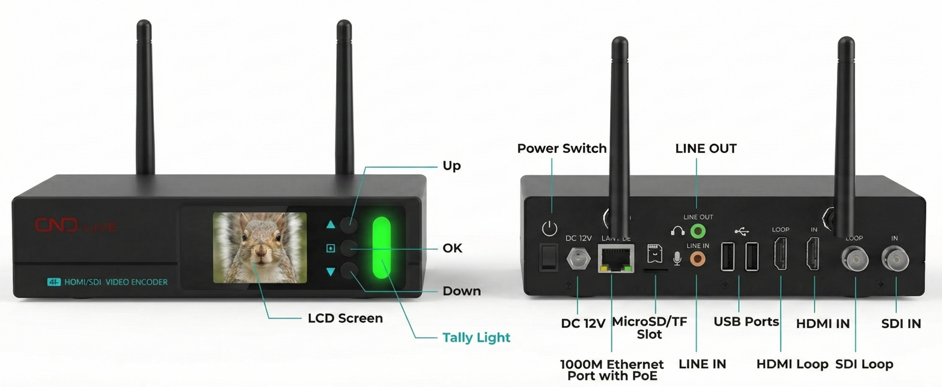
2.3 Hardware Interface Guide
Section titled “2.3 Hardware Interface Guide”Refer to the diagram below for a detailed overview of the device interfaces.
| ID | Component | Description |
|---|---|---|
| 1 | Power Switch | Toggle device power on/off. |
| 2 | DC 12V | Connect the power adapter here. |
| 3 | LAN Port | Gigabit Ethernet (PoE Supported). |
| 4 | TF Slot | Insert Micro SD card for recording. |
| 5/6 | Audio I/O | 3.5mm Jacks: Line Out (Top) / Mic In (Bottom). |
| 7 | USB 2.0 | For external USB storage disks. |
| 8 | HDMI Loop | Local monitoring output. |
| 9 | HDMI In | Video source input (Camera/PC). |
| 10/11 | SDI Ports | BNC connectors: SDI Loop (Top) / SDI In (Bottom). |
| 12 | LCD Screen | Displays IP address, preview, and status. |
| 13 | Up Button | Move selection up. |
| 14 | Menu/OK | Enter menu or confirm settings. |
| 15 | Down Button | Move selection down. |
| 16 | Tally | Status light (Green=Preview, Red=Live). |
2.2 Tally Indicators
Section titled “2.2 Tally Indicators”The front panel Tally lights indicate the live status of your video feed:
| Color | Status | Meaning |
|---|---|---|
| 🟢 Green | Solid | Preview: The source is connected and ready (Standby). |
| 🔴 Red | Solid | Program: The device is actively streaming (Live/PGM). |
3. Quick Start Guide
Section titled “3. Quick Start Guide”Follow these steps to get your C6 encoder up and running immediately.
-
Power On Connect the 12V DC power adapter to the rear port and secure the locking ring. Press the power switch.
-
Connect Video Sources Connect your camera or video switcher to the HDMI IN or SDI IN port.
- Optional: Connect a local monitor to the corresponding Loop Out port for zero-latency monitoring.
-
Network Connection Connect an Ethernet cable from the C6 to your network switch or router.
- The device is set to DHCP by default and will automatically acquire an IP address.
-
Connect Audio (Optional) Connect an external microphone (3.5mm) or audio mixer output to the MIC port if you are not using embedded HDMI/SDI audio.
-
Verify Status Wait for the LCD screen to light up. It will display the CPU status and the acquired IP address (e.g.,
192.168.1.100).
4. LCD Screen Operation
Section titled “4. LCD Screen Operation”The C6 features a 2.0-inch built-in LCD screen combined with physical navigation buttons. This interface is designed for PC-Free operation, allowing you to monitor signal integrity, manage network connections, and control recording/streaming status directly from the device.
4.1 Navigation Controls
Section titled “4.1 Navigation Controls”The physical buttons located to the right of the screen are your primary control tools:
- UP / DOWN: Cycle through the main dashboard pages (System State -> Signal Source -> Network -> Encoding -> Stream -> Recording).
- OK (Square Button):
- Short Press: Enter a sub-menu or confirm a selection (e.g., toggle a switch).
- Long Press: Triggers specific shortcuts (e.g., Factory Reset on startup).
4.2 Preview Mode (Default Status)
Section titled “4.2 Preview Mode (Default Status)”Upon startup, if no operation is performed for 30 seconds, the screen automatically enters Real-time Preview Mode. This is critical for confirming signal integrity without a monitor.
- Signal Logic:
- Default: Displays the HDMI input source.
- Priority in Mix Mode: If “Mix A” is selected, HDMI is the main background. If “Mix B” is selected, SDI is the main background.
- Failover Display: If the primary source is lost, the screen will attempt to display the secondary source or show a blue screen with messages like “No Signal”.
4.3 System Status Dashboard
Section titled “4.3 System Status Dashboard”This is the root menu page, providing a comprehensive health check of the device.
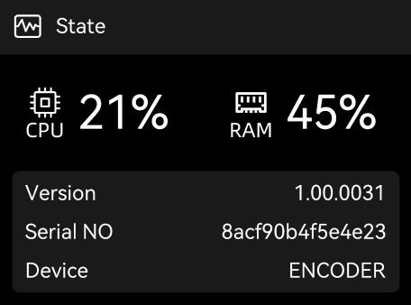
Performance Monitoring:
CPU & Memory%: High usage (above 90%) may indicate the device is overloaded (e.g., too many concurrent high-bitrate streams).Device Identity
Serial No. & Firmware Version: Essential information for technical support cases.Device Name: Matches the NDI source name visible on the network.
4.4 System Maintenance Menu
Section titled “4.4 System Maintenance Menu”Pressing OK on the System Status page enters the critical maintenance menu:
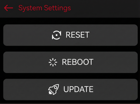
Reset: Restores factory settings. Use this if you are locked out of the device or facing configuration conflicts.
Reboot: Performs a safe soft restart of the system.
Update (via USB): Allows firmware upgrades without a network connection. *
Requirement: Insert a USB drive with the firmware (.bin file) in the root
directory before selecting this option. :::tip[Hardware Shortcut] If the
menu is inaccessible, press and hold both the Up and Down buttons on
the front panel simultaneously for 8 seconds. The device will automatically
reset and reboot.
4.5 Local Recording
Section titled “4.5 Local Recording”Manage recording to the local SD card or USB drive.
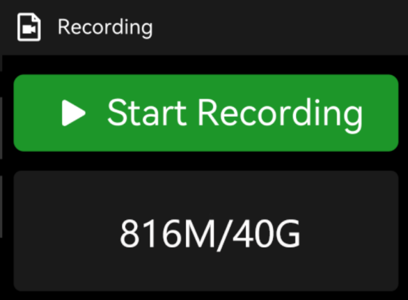
Storage Monitor: Displays used space vs. total capacity (e.g., 10G/64G).
Action: Press OK to instantly Start/Stop Recording. The timer will appear to confirm recording is active.
4.6 Signal Source Details
Section titled “4.6 Signal Source Details”Press Down to access detailed input specifications. This page helps rule out EDID or handshake issues.
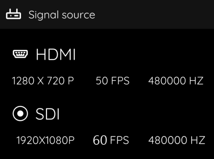
HDMI / SDI Status: Displays current Resolution, Frame Rate, and Audio Sample Rate (e.g., 48kHz).
Troubleshooting: If this page shows “No Signal” but your camera is on, the issue lies in the physical link or source device, not the encoder’s network or streaming settings.
4.7 Network Configuration
Section titled “4.7 Network Configuration”Press Down to navigate to Network settings. The C6 separates Wired and Wireless configurations.
Wired Network (LAN)
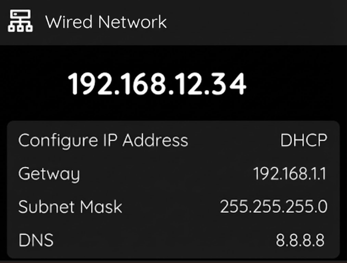
Info Display: Shows current IP Address, Gateway, Subnet Mask, and DNS.
Action (Press OK): Enters the Setting menu. You can select between two modes:
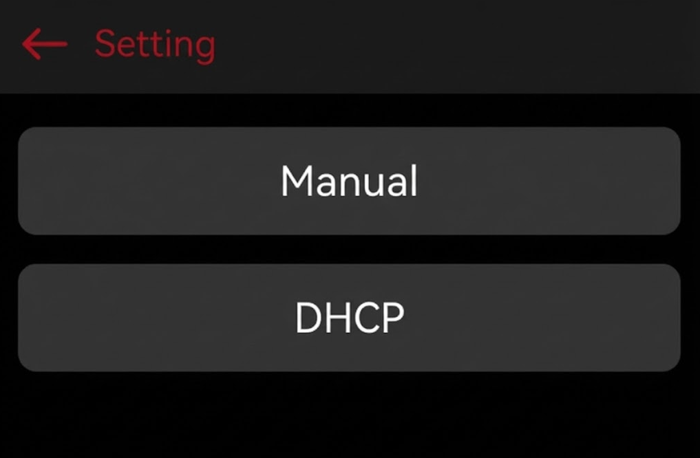
Manual: Select this to set a Static IP. * You will enter a configuration
screen to input the IP Address, Gateway, and Subnet Mask. * A
confirmation screen will appear (e.g., 192.168.200.202). You can press the
Up/Down buttons to adjust the numeric values. Select Confirm to save the
changes. DHCP: Select this to automatically acquire an IP address from your
network server.
Wireless LAN (Wi-Fi)
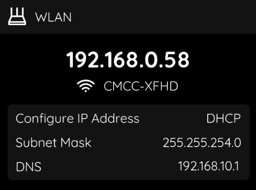
Info Display: Shows current SSID, Signal Strength (dBm), and IP.
Action (Press OK): Enable or Disable the Wi-Fi module to save power or prevent network conflict.
4.8 Encoding
Section titled “4.8 Encoding”Press Down in the Wireless LAN menu to navigate to the Encoding status page.
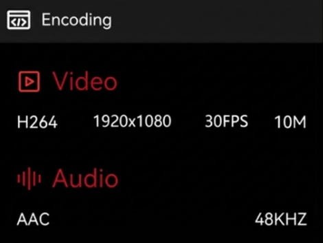
Video: Displays the current video encoding version (e.g., H.264 or H.265).
Encoding Bitrate: Shows the current video bitrate, which determines the compression level and video quality.
Audio: Displays the current audio encoding format (e.g., AAC or G.711).
Audio Sample Rate: Shows the current audio sampling rate, which affects audio fidelity and file size.
4.9 Stream Services Management
Section titled “4.9 Stream Services Management”This page allows for direct control over your broadcasts without a laptop.
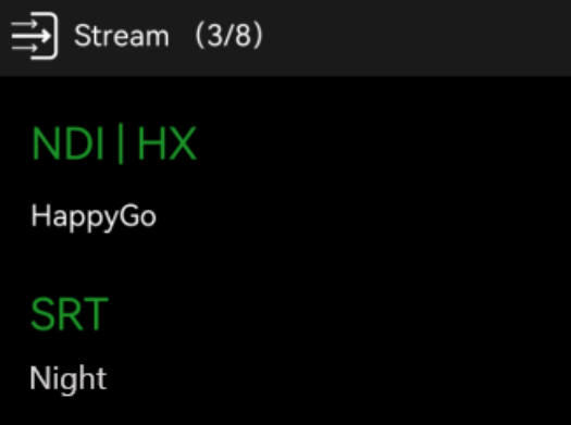
Status Indicator (e.g., “Stream 3/8”): The first number indicates Active streams; the second indicates Total Configured streams.
Stream Control:
-
Press OK to enter the list of configured streams (RTMP, SRT, NDI, etc.).
-
Use Up/Down to highlight a specific stream.
-
Press OK to Start (Green) or Stop (White) that specific stream immediately.
5. Web Management & Configuration
Section titled “5. Web Management & Configuration”This is the control center for C6 encoder.
5.1 Login
Section titled “5.1 Login”- Ensure your computer is on the same network subnet as the C6.
- Type the IP address found on the LCD screen (e.g.,
http://192.168.x.x) into your web browser (Chrome is recommended). - Default Credentials:
- Username:
admin - Password:
admin
- Username:
5.2 Dashboard Overview
Section titled “5.2 Dashboard Overview”The Dashboard serves as your central control hub.
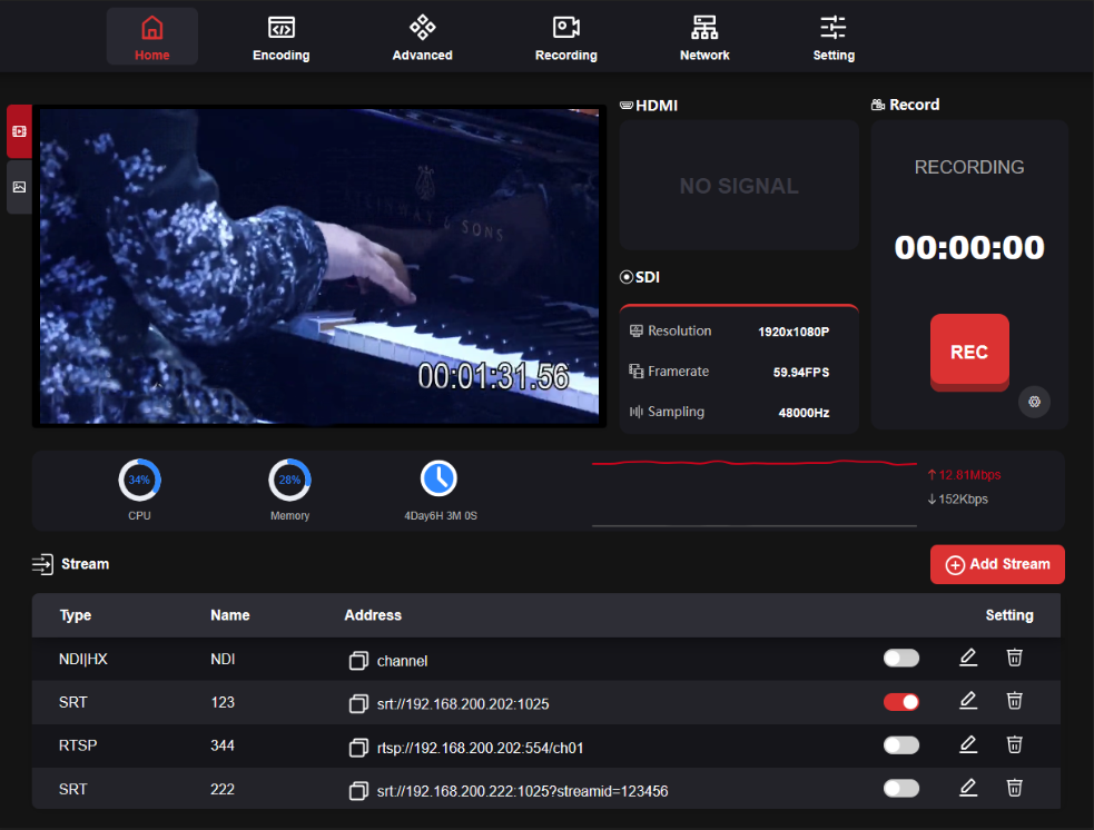
- Preview Window: Real-time low-latency video monitoring.
- Video Sources: Instant status check for HDMI & SDI inputs (Resolution, FPS, Hz).
- Recording: One-click Start/Stop recording and duration timer.
- System Health: Visual gauges for CPU, Memory load, and total Runtime.
- Network: Real-time traffic visualization (Upload/Download bitrate).
- Stream: Manage all output streams (e.g.,NDI, SRT, RTSP). Supports Quick Toggle (On/Off), Edit, and Delete actions.
5.3 Encoding Settings
Section titled “5.3 Encoding Settings”Navigate to the Encoding tab to configure video quality.
5.3.1 Video Signal Selection
Section titled “5.3.1 Video Signal Selection”Select the active video input source or configure Picture-in-Picture (PiP) layouts for dual inputs.
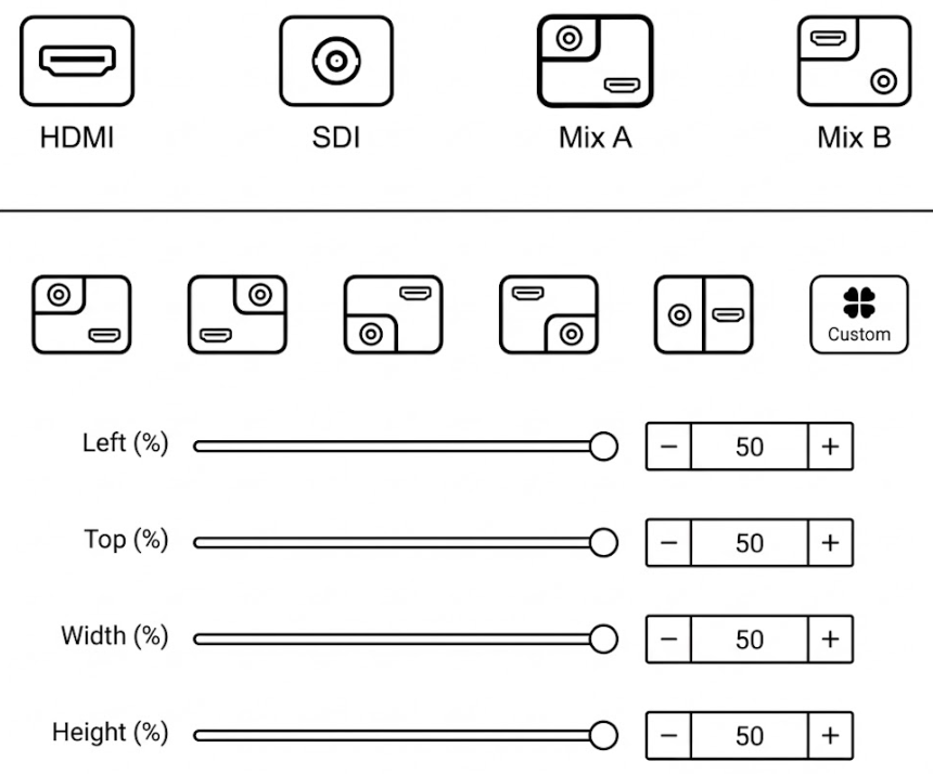
Source Modes
- Single Source: Select HDMI or SDI to encode a single video input directly.
- Mixed Source (PiP): Combines both inputs into a single stream.
- Mix A: HDMI is the main background; SDI is the overlay window.
- Mix B: SDI is the main background; HDMI is the overlay window.
Mixed Layout Configuration When Mix A or Mix B is selected, a row of layout icons appears below.
- Preset Layouts: Click one of the 5 preset icons to instantly position the sub-screen (e.g., Top-Left, Side-by-Side, etc.).
- Custom Layout: Click the Custom button to manually resize and reposition the sub-screen using sliders: _ Left (%): Horizontal position (0% = Left edge, 50% = Center). _ Top (%): Vertical position (0% = Top edge, 50% = Center). _ Width (%): The width of the sub-screen relative to the total canvas. _ Height (%): The height of the sub-screen relative to the total canvas.
5.3.2 Stream Settings
Section titled “5.3.2 Stream Settings”The Main Stream serves as your primary encoding channel, designed to deliver high-quality video for critical tasks. It offers comprehensive parameter controls—including Resolution, Codec, and Bitrate—to ensure optimal performance for scenarios such as live broadcasting, NDI transmission, and high-definition recording.
Try it yourself You can click on the options below to view all available settings.
-
Resolution: Same As The Video Source is recommended for 1:1 pixel fidelity. Select lower resolutions (e.g., 1280x720) only to save bandwidth on unstable networks.
-
Type (Codec):
- H.264 (AVC): Max compatibility (Old players, RTMP to YouTube/Facebook).
- H.265 (HEVC): High efficiency. Delivers equal quality at 50% lower bitrate, ideal for bandwidth-constrained environments.
-
Rate Control:
- CBR: Best for Live Streaming. Ensures steady data flow to prevent network spikes.
- VBR: Best for Local Recording. Allocates data dynamically to save storage space.
-
Bitrate: Controls data usage (Higher = Better Quality).
- Standard: 4Mbps - 10Mbps (for 1080p60).
- Max: Up to 40Mbps for visually lossless needs.
-
Framerate: Set to match your camera input (e.g., 60fps) for smooth motion.
-
GOP: Defines Keyframe interval.
- Standard: Set to 2x Framerate (e.g., 60 for 30fps) for a 1-second interval.
- Low Latency: Lower values reduce latency but increase bandwidth usage.
-
NDI Options: _ NDI|HX2: Balanced efficiency with full manual control over Bitrate and GOP. _ NDI|HX3: Ultra-Low Latency & High Quality.
The Sub Stream is a secondary, lower-bandwidth feed designed for remote monitoring, mobile viewing, or web previews.
- Resolution: Typically capped at 1280x720 (720p) or lower (e.g., 640x360). This ensures smooth playback on devices with limited processing power or bandwidth.
- Type: Defaults to H.264. This format offers the widest compatibility with web browsers and mobile apps without requiring additional plugins.
- Rate Control:
- CBR: Recommended. Keeps the stream stable for remote monitoring over the public internet.
- Bitrate: Controls the stream quality and bandwidth usage.
- Selection: Choose from preset values (e.g., 128K, 512K, 1M) via the dropdown menu.
- Recommendation: 1M (1Mbps) is the “sweet spot” for a clear 720p preview. Use 512K for poor network conditions.
- Framerate: Often set to 30fps. This is sufficient for monitoring and saves significant bandwidth compared to 60fps.
- Profile:
- Baseline: Highly recommended for Sub Stream. It is the simplest profile to decode, ensuring fast load times and compatibility with older mobile devices.
- GOP: Defines the keyframe interval. Keep it consistent with the Main Stream logic (usually 2x Framerate) for standard latency.
5.3.4 MJPEG Configuration
Section titled “5.3.4 MJPEG Configuration”This configuration directly controls the image refresh rate for the device’s physical LCD Screen and the remote preview thumbnail on the CNDLive Manager platform. The MJPEG stream generates a sequence of snapshots for low-bandwidth monitoring without consuming your primary video encoding resources.
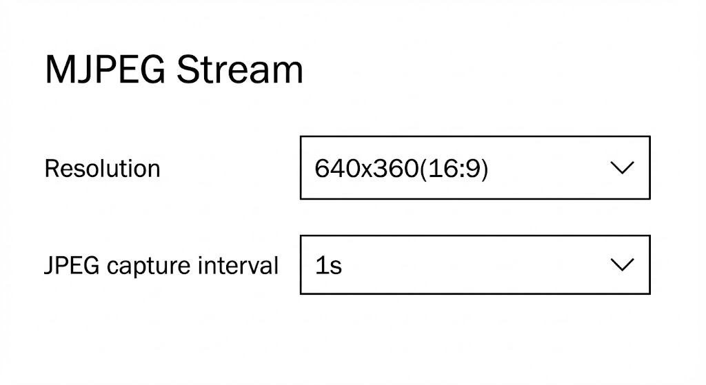 *
Resolution: Currently fixed at 640x360. This specific resolution is
locked to ensure maximum system stability and prevents management traffic from
interfering with your main video broadcast. * JPEG Capture Interval:
Determines how frequently a snapshot frame is refreshed. A shorter interval
provides a smoother preview but uses slightly more system resources. *
Selection: Choose from standard presets (1s, 2s, 3s) via the
dropdown menu. * Custom: Select “Custom” to input a specific integer. Note
that the value must be less than 10s.
*
Resolution: Currently fixed at 640x360. This specific resolution is
locked to ensure maximum system stability and prevents management traffic from
interfering with your main video broadcast. * JPEG Capture Interval:
Determines how frequently a snapshot frame is refreshed. A shorter interval
provides a smoother preview but uses slightly more system resources. *
Selection: Choose from standard presets (1s, 2s, 3s) via the
dropdown menu. * Custom: Select “Custom” to input a specific integer. Note
that the value must be less than 10s.
5.3.5 Audio Source Selection
Section titled “5.3.5 Audio Source Selection”Configure audio input sources, volume levels, and encoding formats. This section also supports audio mixing and lip-sync adjustment.
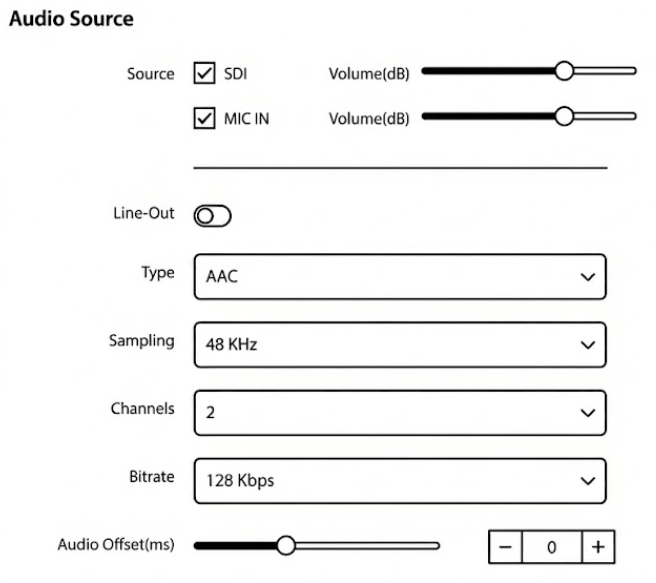
Input & Output Control
- Source: Select the audio input channel.
- Video Source (HDMI/SDI): Audio embedded in the video signal.
- MIC IN: External audio via the 3.5mm Line-in port.
- Mixing: Check both boxes to mix embedded audio with external audio.
- Volume (dB): Independent volume sliders for each source. Press + / - or drag the slider to adjust the gain.
- Line-Out: Toggle switch to enable or disable local audio loop-out for monitoring.
Encoding Parameters
- Type (Codec):
- AAC: High-quality audio compression (Recommended for streaming).
- G.711: Legacy standard, typically used for low-bandwidth voice intercom.
- Sampling: Defines the audio sampling frequency.
- Options: 48 KHz (Standard), 44.1 KHz, 32 KHz, 22.05 KHz, 16 KHz, 8 KHz.
- Recommendation: Use 48 KHz or 44.1 KHz for high-fidelity broadcasting.
- Channels: Select 1 (Mono) or 2 (Stereo).
- Bitrate: Controls audio quality and bandwidth.
- Range: Selectable from 32 Kbps up to 256 Kbps.
- Standard: 128 Kbps is widely used for standard streaming.
- Audio Offset (ms): Adjusts the audio timestamp to fix lip-sync issues.
- Action: If audio is ahead of video, increase the value; if behind, decrease it.
5.4 Advanced Settings
Section titled “5.4 Advanced Settings”The Advanced menu provides professional video processing tools, allowing you to customize the video signal, manage OSD overlays, configure shortcut keys, and adjust screen settings.
Video Source Selection: Before applying any effects (Cropping, Rotation, etc.), you must first select the target input source (HDMI or SDI) at the top of the panel. Settings are independent for each source.
5.4.1 Cropping
Section titled “5.4.1 Cropping”The Cropping function allows you to define a specific region of interest (ROI) from your video source, removing unwanted borders or focusing on a specific area to meet different scene requirements.
- Enable/Disable: Toggle the Cropping switch to activate or deactivate the feature.
- Visual Preview: A graphical representation shows the cropped area (inner lighter box) relative to the full video frame.
Parameter Configuration You can adjust the cropping area using the sliders, by clicking the + / - buttons, or by entering specific percentage values:
Try it yourself Drag the sliders or input values below to simulate the cropping behavior.
Left (%): Adjusts the horizontal starting position from the left edge (Range: 0% - 100%).
Top (%): Adjusts the vertical starting position from the top edge (Range: 0% - 100%).
Width (%): Defines the width of the visible screen area (Range: 0% - 100%).
Height (%): Defines the height of the visible screen area (Range: 0% - 100%).
5.4.2 Rotation/Flip
Section titled “5.4.2 Rotation/Flip”The Rotation and Flip functions allow you to correct the video orientation digitally. This is essential for scenarios where the camera is mounted upside down (ceiling mount), used in portrait mode (mobile streaming), or requires image mirroring.
Try it yourself Change the settings below to see how Rotation and Flip affect the video output.
Rotation: Rotates the entire video frame in a clockwise direction.
- 0° Rotation: Keeps the original landscape orientation.
- 90° Rotation: Rotates 90 degrees clockwise (Suitable for vertical screens).
- 180° Rotation: Rotates 180 degrees (Suitable for inverted cameras).
- 270° Rotation: Rotates 270 degrees clockwise.
Flip: Mirrors the video image along a specific axis.
- No Flip: Keeps the original image state.
- Flip Horizontally: Mirrors the image left-to-right (often used for teleprompters or “selfie” mode).
- Flip Vertically: Mirrors the image top-to-bottom.
- Flip horizontally and vertically: Mirrors along both axes simultaneously.
5.4.3 No Signal Background
Section titled “5.4.3 No Signal Background”This feature defines the default display output when the device fails to detect a valid video signal or when the source is disconnected.
- Color Options: Select from 6 preset solid colors to fill the screen during signal loss.
- Available Colors: Black, Red, Green, Blue, Cyan, Purple.
- Configuration: Click on a color block to select it, then click Apply to save the setting.
5.4.4 OSD Management
Section titled “5.4.4 OSD Management”The OSD (On-Screen Display) feature allows you to superimpose dynamic information or branding onto your video streams, such as Logos, Time/Date stamps, or text.
To use an image overlay (e.g., a station logo), you must first upload the file to the device’s local library.
- Upload: Click the Image Placeholder under “Overlay Setting” to open the upload dialog.
- Requirements:
- Format: Supports JPG, JPEG, and PNG.
- Size: File size must be below 5MB.
- Management: Once uploaded, images appear in the gallery and can be selected for overlays.
Try it yourself Select a content type (Text/Date/Image) and click the grid to position it on the screen.
content Configuration
Depending on the selected type, configure the specific display parameters: * Text: Enter your custom text in the “Overlay Text” field. * Date/Time: Select from preset formats (e.g.,YYYY/MM/DD hh:mm:ss) to display the
real-time system clock. * Image: Select a previously uploaded logo from the
visual list.
Styling (Text/Date/Time)
* Text Color: Click the color box to pick a font color. * Font Size: Select a size from the dropdown menu (Range: 12 to 72) to ensure readability on different screens.OSD List Management
The OSD List at the bottom shows all active overlays. * Status: View the current state (e.g., “Success”). * Manage: Use the Edit (Gear icon) to modify settings or Delete (Trash icon) to remove an overlay. * Batch Deletion: Use the checkbox to select multiple items and click Batch Deletion for quick cleanup.5.4.5 Shortcut Key
Section titled “5.4.5 Shortcut Key”The Shortcut Key feature allows you to define custom hotkeys for frequently used operations, enabling instant control without navigating through menu layers.
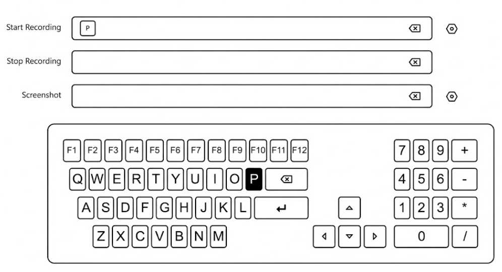
Supported Functions
You can assign unique shortcuts to the following critical actions: * Start Recording: Triggers the onboard recording immediately. * Stop Recording: Ends the current recording session. * Screenshot: Captures a still image of the current video feed.Configuration Steps
- Select Function: Click the input field next to the desired function (e.g., “Start Recording”). 2. Assign Key: A virtual keyboard will appear at the bottom of the screen. Click any key (Letters, Numbers, or F1-F12) to assign it. * Example: In the diagram, the key “P” is assigned to Start Recording. 3. Clear/Delete: Click the ❌ inside the input field.
5.4.6 LcdScreen Settings
Section titled “5.4.6 LcdScreen Settings”This section controls the behavior of the device’s front panel 2-inch LCD screen, allowing it to serve as a status monitor when the device is idle.
- Picture Preview: Toggle this switch to enable the automatic LCD preview feature. _ Activation Logic: The screen will automatically switch to previewing the encoded image stream after 30 seconds of inactivity (no physical button operations). _ Interruption: Pressing any key on the front panel will immediately interrupt the preview and return to the system menu.
5.5 Recording
Section titled “5.5 Recording”The Recording module allows you to store high-definition video directly to a local USB drive or TF (Micro SD) card. It supports continuous loop recording and file segmentation, ensuring you never miss a critical moment.
5.5.1 Recording Settings
Section titled “5.5.1 Recording Settings”Configure how the video files are saved, named, and managed.
- Record Switch: Toggle this switch to Enable or Disable the recording function.
- Storage Device: Select the target destination (e.g., USB drive or TF card) from the dropdown list.
- Recording Format: Choose the container format for the video files.
- ts: Transport Stream. Highly recommended for live production because the file remains readable even if power is lost suddenly.
- mp4 / mkv: Standard formats for broad compatibility with media players.
- Naming Convention:
- Prefix: Custom text added to the beginning of the filename (Default:
REC-). - Folder Name: The directory where files will be stored (Default:
RECORDING).
- Prefix: Custom text added to the beginning of the filename (Default:
- Max Duration: Defines how the system splits long recordings into smaller, manageable files.
- Options: 10min, 30min, or One Hour.
- Benefit: Splitting files prevents data loss if a single large file becomes corrupted.
- Strategy: Defines behavior when the storage becomes full.
- Loop: Circular recording. The system automatically deletes the oldest files to make room for new ones. Ideal for 24/7 monitoring.
- Stop when full: Recording stops immediately when storage capacity is reached. Recommended for archiving critical events where old footage must not be lost.
5.5.2 Storage Management
Section titled “5.5.2 Storage Management”This section provides tools to manage the physical storage media and the recorded files.
Disk Tools
* Status Bar: A visual progress bar showing Used vs. Total capacity (e.g.,6.3G / 115G). * Speed Test: Click to verify if the
disk’s write speed meets the bitrate requirements of your recording settings. *
Format: Erases ALL data on the drive and re-initializes the file system.
Use with caution!
Recording List
Displays a chronological list of all video files stored on the drive. * File Details: View Filename, Start/End Time, and File Size. * Management: * Delete: Click the Trash icon to remove individual files. * Batch Deletion: Check multiple boxes on the left and click Batch Deletion at the bottom to remove files in bulk.5.6 Network Settings
Section titled “5.6 Network Settings”The Network module manages the device’s connectivity interfaces. You can configure wired (LAN) and wireless (Wi-Fi) connections, as well as enable SNMP for remote monitoring systems.
5.6.1 Wired Network
Section titled “5.6.1 Wired Network”Configure the IP address for the Ethernet interface.
- DHCP Switch: Toggle ON to automatically acquire an IP address from your router/switch. Toggle OFF to manually configure a Static IP.
- Interface Status: Displays current connection state (e.g., “Connected”).
- Manual Configuration: When DHCP is OFF, you must manually input:
- IP Address / Subnet Mask: Ensure these match your local network segment.
- Gateway: The router’s IP address.
- DNS 1 / DNS 2: Domain Name Servers for internet access.
- Apply: Click to save changes. Note: Changing IP settings may disconnect the Web UI momentarily.
5.6.2 Wireless Network (Wi-Fi)
Section titled “5.6.2 Wireless Network (Wi-Fi)”Connect the device to a wireless hotspot.
Connection Management
* Wi-Fi Switch: Toggle ON to enable the wireless module and scan for available networks. * Network List: Displays available SSIDs, Signal Strength, and Connection State. * Connect: Click “Connect” next to a network, enter the password, and confirm. * Forget Password: Removes saved credentials for a connected network. * Refresh List: Rescans the environment for new hotspots.Manual Addition (Hidden SSIDs)
For networks that do not broadcast their SSID, use the + Add Another Network button. * SSID: Enter the exact network name manually. * Encryption Type: Select the security protocol (e.g., WPA, WEP, or None). * Password: Enter the security key.5.6.3 SNMP
Section titled “5.6.3 SNMP”Enable Simple Network Management Protocol (SNMP) for integration with centralized monitoring systems.
- SNMP Switch: Toggle ON to activate the agent.
- Port: Default is 161. Change this only if your network policy requires a custom port.
- Community: The authentication string (similar to a password). Default is
public.
5.7 Settings
Section titled “5.7 Settings”The Settings menu allows you to manage system-level configurations, including user accounts, time synchronization, security, and logs. Most importantly, it is the control center for connecting to the CNDLive Manager platform and configuring the Voice Intercom system.
5.7.1 CNDLive Manager Connection
Section titled “5.7.1 CNDLive Manager Connection”Configure the connection to the centralized management platform for remote control and monitoring.
- Configuration Switch: Toggle ON to enable the connection agent.
- Server Address: Enter the IP address or Domain Name of your CNDLive Manager server (e.g.,
192.168.0.118). - Port: Default communication port is 50000.
- Links: Select which network interfaces to use for the management connection (e.g., LAN1, Wi-Fi).
- Note: You must select at least one active link.
- Connection Status:
- Connected: A green checkbox appears at the top left when the link is established.
- Speed Rate: A real-time graph at the bottom displays the bandwidth usage (Kb/s) specifically for the management connection, helping you diagnose network stability.
5.7.2 Voice Intercom
Section titled “5.7.2 Voice Intercom”The Intercom feature enables real-time voice communication between the device operator and the studio/director center.
Status Indicators
The main dashboard provides instant status feedback:Intercom Group
Not Joined (Grey): Device is disconnected from the intercom group.
Joined (Green): Device is successfully connected and ready to go.
Headset
Unplugged (Grey): No audio device detected.
Plugged (Green): A USB headset/microphone is correctly recognized.
Intercom Settings
Click the Gear Icon next to the intercom status to fine-tune audio performance:- Voice Input: Select your specific USB audio device from the dropdown list (e.g., “Lenovo Services E01”).
- Mic Level: Adjust the microphone gain (Input volume).
- Output Level: Adjust the headphone volume (Monitoring volume).
- Audio Quality: Select the transmission bitrate profile:
- High: Best quality, requires stable bandwidth.
- Middle: Balanced option (Recommended).
- Low: Lowest bandwidth usage, suitable for poor network conditions.
5.7.2 User Management
Section titled “5.7.2 User Management”This section allows you to manage access credentials for the device. You can create multiple user accounts to secure the device settings.
Adding a User
To create a new account, follow these steps: 1. Click the + Add User button at the top right corner. 2. In the pop-up window, fill in the required fields: * User Name: The login ID for the new user. * Remark: A label or description (e.g., “Staff”, “IT”). * Password: Set a secure login password. 3. Click Apply to save the new user.Managing Users
The User List displays all current accounts. You can perform the following actions:- Edit: Click the Gear Icon to modify the user’s remark or reset their password.
- Delete: Click the Trash Icon to remove a user account permanently. * Note: The default admin account cannot be deleted, only edited.
5.7.3 Time and Zone
Section titled “5.7.3 Time and Zone”Ensuring the device runs on the correct time is essential for accurate log recording, troubleshooting, and task scheduling.
Time Configuration
Select one of the three available Modes to synchronize the system clock:- Timing with current PC: Instantly syncs the device’s time with the computer you are currently using to access the Web UI. This is the quickest method for initial setup.
- Manual Timing: Allows you to manually input a specific date and time string (Format:
YYYY-MM-DD HH:MM:SS). This is useful for isolated networks without internet access. - Sync from NTP Server: Connects to a Network Time Protocol server for high-precision, automatic synchronization.
- Setting: You must enter a valid NTP Server Address (e.g.,
pool.ntp.org). Supports multiple addresses separated by spaces.
- Setting: You must enter a valid NTP Server Address (e.g.,
Zone Configuration
Define the geographical region to ensure the offset from UTC is correct.- Region and Position: Click the dropdown menu to select your time zone. The list supports selection by: _ Major Cities: e.g., “Asia/Shanghai”, “Seoul”, “New York”. _ GMT Offsets: e.g., “GMT-8”, “GMT+1”.
5.7.4 System
Section titled “5.7.4 System”The System panel is the hub for device maintenance. Here you can view hardware details, perform firmware upgrades, reset configurations, or restart the device.
Device Info
Displays critical identity information for the device: * Versions: View current Hardware and Software versions to determine if an update is needed. * Serial Number: Click the ❐ to quickly copy the SN to your clipboard (Essential information for connecting to CNDLive Manager and technical support). * Device Name: Click the ✏️ to rename the device. This name identifies the unit on the network and in the NDI discovery list.Firmware Update
Keep your device running efficiently by installing the latest software. 1. Select File: Click to browse your local computer for the update file. * Requirement: The file must be in .bin format. 2. Update: Once the filename appears, click the Update button to begin. * Warning: Do not disconnect power during the update process to prevent system corruption.Reset Factory Settings
This operation restores the device to its original out-of-the-box state. * Action: Click Reset to wipe all custom configurations (Network IP, Encoding params, User accounts, etc.). * Result: The device will revert to default settings and automatically reboot.Reboot
Performs a safe software restart of the device. * Action: Click Reboot to restart the system without losing your saved configurations. * Duration: The process typically takes about 30 seconds.5.7.5 Security
Section titled “5.7.5 Security”The Security settings allow you to configure the network protocols used to access the device’s Web User Interface, ensuring secure data transmission.
HTTP/HTTPS Setting
Configure the ports and protocols for web access: * HTTP: Standard web traffic. * Checkbox: Check to enable HTTP access (Default: Enabled). * Port: Default is 80. You can customize this if port 80 is blocked or used by other services. * HTTPS: Encrypted web traffic (Recommended for public network access). * Checkbox: Check to enable HTTPS access. * Port: Default is 443.Certificate Management
To use HTTPS securely without browser warnings, you must upload valid SSL certificates. * CA Certificate: Drag and drop your certificate file here. * Format Requirement: Supports .crt files. * CA Secret Key: Drag and drop the corresponding private key file here. * Format Requirement: Supports .key files.5.7.6 Log
Section titled “5.7.6 Log”The Log system records key operational events, system errors, and warning messages. This is the first place to check if you encounter unexpected behavior or need to troubleshoot connectivity issues.
Log Viewing & Filtering
The main dashboard displays a chronological list of system events. You can filter the view to focus on specific types of messages: * Filters: Use the checkboxes at the top right to toggle All, Information, Warning, or Error logs. * Event Types: * Information 💬 : General system activities, such as “Wi-Fi connected successfully” or “Settings updated”. * Warning ⚠️ : Alerts that don’t stop operation but require attention, such as “Device is updating”. * Error ❗ : Critical failures, such as “HDMI Signal Lost” or connection drops.Log Management
Use the control buttons at the bottom right to manage the log history:- Export: Downloads the current log history to your computer for offline analysis or technical support.
- Format: The file is saved as an HTML document (e.g.,
Log_2026_01_16_14_03_56.html) which can be viewed in any web browser.
- Format: The file is saved as an HTML document (e.g.,
- Clear: Click the 🗑️ icon to permanently delete all currently recorded events from the device memory.
6. Support
Section titled “6. Support”Thank you for choosing CNDLive. We are dedicated to providing you with the best streaming experience. If you encounter any technical issues not covered in this manual, our support team is ready to assist you.
Contact Information
* Official Website: Visit our website to download the latest firmware, and tools. * Technical Support Email: Send your inquiries to support@cndlive.com.Before You Contact Us
To help us diagnose and resolve your issue as quickly as possible, please have the following information ready before contacting support:- Device Identity: Your device’s Serial Number and current Firmware Version.
- System Log: An exported Log file (HTML format) that captures the time period when the issue occurred.
- Problem Description: A brief description of your network environment (Switch, Router settings) and the video source you are using.