X1 4G Bonding Encoder User Manual
Welcome to the CND Live X1. This manual guides you through the installation, configuration, and operation of your professional bonding encoder.
1. Product Overview
Section titled “1. Product Overview”1.1 Introduction
Section titled “1.1 Introduction”The X1 4G Bonding Encoder is a high-performance device designed for mission-critical video transmission. Unlike standard encoders, the X1 utilizes Network Bonding technology to aggregate multiple internet connections, ensuring stable live streaming even in challenging outdoor environments.
1.2 Key Features
Section titled “1.2 Key Features”- Multi-Source Input: Supports HDMI (Consumer) and SDI (Professional) video sources.
- Network Bonding: Aggregates up to 7 network links (Ethernet, Wi-Fi, USB Tethering, and 3x Internal 4G Modems).
- Professional Protocols: Full support for NDI|HX, SRT, RTMP, RTSP, and TS-UDP.
- Built-in Touchscreen: A 5.5-inch LCD for monitoring and control without a computer.
- Intercom: Real-time bidirectional voice communication with the studio via CNDLive Manager.
1.3 Interface Description
Section titled “1.3 Interface Description”
| Component | Description | | :--- | :--- | | Video Inputs | HDMI: Connect cameras, laptops, or switchers.
SDI: Connect professional broadcast cameras (BNC). | | Audio | Line In (3.5mm): For external microphones or mixers.
USB Headset: For Intercom communication. | | Network | LAN: Gigabit Ethernet (RJ45).
SIM Slots: 3 physical slots (Supports 2 SIMs per slot, active switching). | | Power | Type-C: 12V/1A Power Input. | | Mounting | Cold Shoe mounts (Top/Bottom) for camera rigs. |
2. Installation & Connection
Section titled “2. Installation & Connection”-
Power On
Connect the provided Type-C Power Adapter (12V/1A) to the power port. Press the Power Button on the back panel to boot the device.
-
Connect Video Source
Connect your camera using the appropriate interface:
- HDMI: Use for DSLRs, mirrorless cameras, or PC output.
- SDI: Use for professional camcorders for a locking connection.
-
Connect Network
You can use a single connection or combine them for bonding:
- Wired: Connect an Ethernet cable to the LAN port.
- 4G/LTE: Insert Nano-SIM cards into the side slots.
Note: Ensure the chip faces the correct direction. You may insert up to 6 SIMs (Slot 1A/1B, 2A/2B, 3A/3B) and switch between them in the software.
- Wi-Fi: Configure via the LCD touch screen.
3. LCD Touch Screen Operation
Section titled “3. LCD Touch Screen Operation”The X1 features a built-in LCD touch screen that allows for monitoring, network configuration, and basic parameter adjustments directly on the device.
3.1 First Boot & Network
Section titled “3.1 First Boot & Network”Upon first startup, the “Welcome” screen displays the device’s IP Address (e.g., 10.0.0.248).
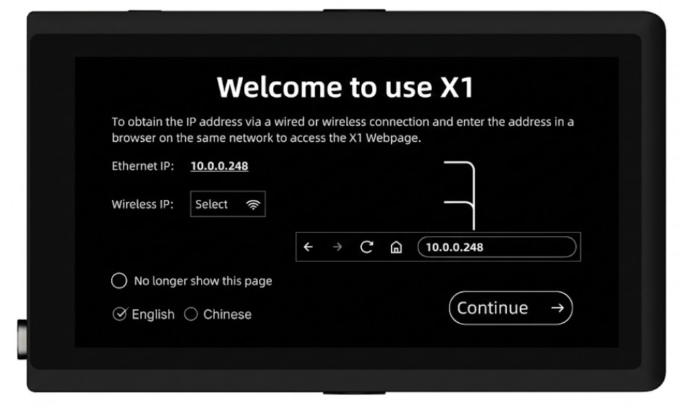
- Network Information: Displays the current IP addresses for Ethernet and Wireless connections. * Web Access Guide: A visual diagram indicates how to enter this IP address into a browser to access the advanced management interface. * Wi-Fi Setup: Tap the Select button next to “Wireless IP” to quickly connect to a Wi-Fi network if the device is not yet connected. * Language Selection: Check the box to switch the system language between English and Chinese. * Startup Preference: * No longer show this page: Check this box if you want the device to boot directly into the Main Interface in the future, skipping this welcome screen.
3.2 Home Page
Section titled “3.2 Home Page”After booting up, the device enters the Home Page. This interface acts as your primary monitor, displaying the real-time video feed overlaid with critical system status and quick-action buttons.
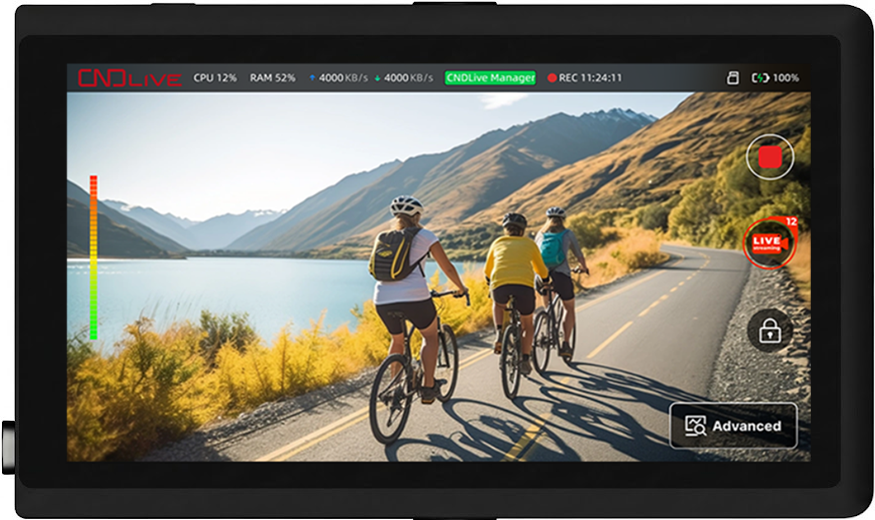
Top Status Bar
The dashboard at the top provides a snapshot of the device’s health: * System Load: Displays real-time CPU and RAM usage percentages. * Network Traffic: Shows current upload (↑) and download (↓) speeds in KB/s. * Platform Status: The CNDLive Manager badge indicates connection status (Green = Connected). * Recording Status: If recording is active, a red REC indicator and a running duration timer (e.g.,11:24:11) are shown. *
Storage: The TF icon appears to indicate that a valid storage device is
inserted and ready. * Power: Displays the battery icon, charging status, and
remaining percentage (e.g., 100%) at the far right.
Touch Controls
Interactive buttons are overlaid directly on the video feed for immediate access: * Audio Meter (Left): A vertical color bar visualizes the real-time audio input levels (Green/Yellow/Red) to help prevent clipping. * Quick Record (Top Right): Tap the Red Square/Circle button to instantly start or stop onboard recording. * Live Streaming (Right): The LIVE icon indicates streaming status. A red badge show stream numbers. * Screen Lock (Right): Tap the Lock Icon to disable touch input, preventing accidental changes during operation. Long-press to unlock. * Advanced (Bottom Right): Tap to enter the detailed system configuration menu (Network monitoring, Encoding, Stream settings).3.3 Control Center (Swipe Down)
Section titled “3.3 Control Center (Swipe Down)”Swipe down from the top of the screen to access quick settings:
- Encoding: Change Resolution (1080p/720p) and Bitrate. 2. Input Source: Toggle between HDMI and SDI. 3. Network Cards: Tap active SIM icons to view signal strength or Configure APN. 4. Fan Control: Adjust cooling (Auto/Low/High). 5. Screen: Adjust brightness and rotation.
3.4 Advanced View
Section titled “3.4 Advanced View”For professional scenarios requiring granular control over network bonding and multi-platform streaming, tap the Advanced button on the bottom right of the Home Page to enter this mode.
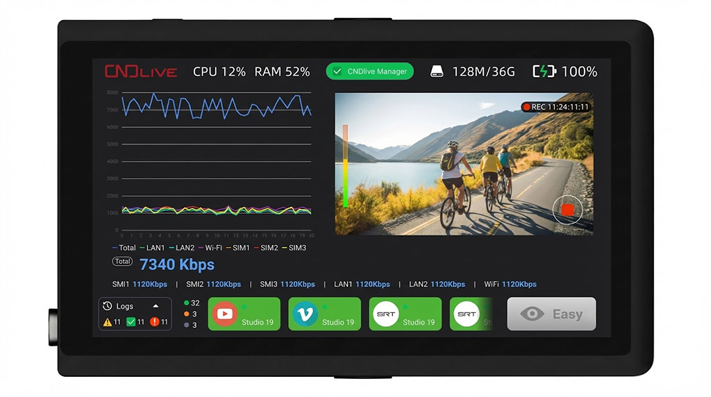
Bonding Network Monitor
The left side of the screen features a comprehensive real-time graph visualizing the network aggregation performance: * Traffic Graph: A dynamic line chart tracks the stability of each connection. Different colors represent different links (e.g., LAN1, Wi-Fi, SIM1, SIM2). * Total Bitrate: The large blue number (e.g., 7340 Kbps) shows the current aggregate upload speed. * Link Details: Below the graph, the specific speed of each individual interface is listed horizontally, helping you quickly identify if a specific SIM card or cable is underperforming.Stream & System Status
This dashboard provides extended details compared to the simple Home Page: * Storage Info: The top bar displays the TF card icon along with precise capacity usage (e.g., 128M/36G used/total). * Streaming Platforms: The bottom section lists all configured output destinations (e.g., YouTube, Vimeo, SRT). * Status Indicator: A green dot on the platform icon confirms that the stream is active and healthy. * Log Summary: The widget in the bottom left counts system events: * Green: info. * Yellow: Warnings.- Red: Errors (Immediate attention required).
4. Web Management & Configuration
Section titled “4. Web Management & Configuration”For advanced setup, access the device via a web browser.
Login Steps:
- Ensure your computer is on the same network as the X1.
- Type the IP Address displayed on the LCD into your browser (Chrome recommended).
- Default Login: Username:
admin/ Password:admin.
4.1 Web Dashboard Home
Section titled “4.1 Web Dashboard Home”After logging in, you will land on the Home dashboard. This interface is designed as a central command center, providing a complete overview of video inputs, system health, and network telemetry.
Video Preview & Input Source
The left side of the screen is dominated by the confidence monitor and input controls: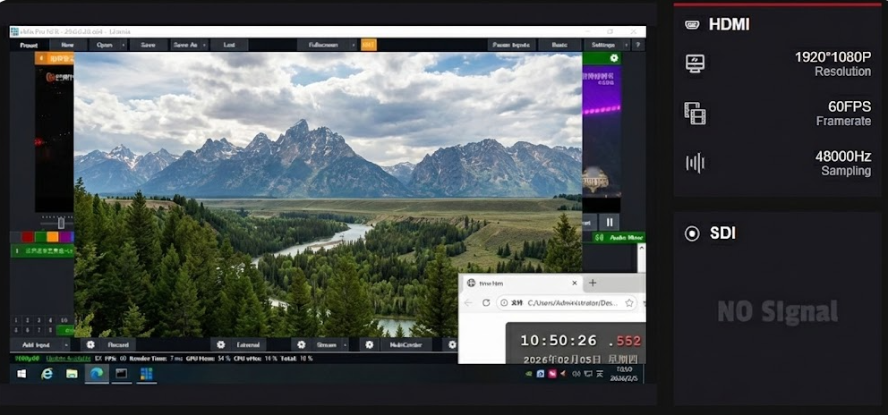
- Preview Window: Displays the encoded content so you can visually verify the signal.
- Input Status:
- HDMI / SDI: Shows the detailed resolution, frame rate, and sampling rate (e.g.,
1920*1080P 60FPS) for the connected source. - Note: “NO Signal” will appear if the selected interface has no cable connected.
- HDMI / SDI: Shows the detailed resolution, frame rate, and sampling rate (e.g.,
CNDLive Manager Configuration
The panel on the right allows for quick connection to the central management platform: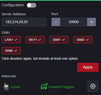
Configuration Switch: Toggle to enable the connection agent.
Server Details: Input your Server Address and Port (Default: 50000).
Link Bonding: Select which network interfaces (LAN1, Wi-Fi, SIM1-6) should be aggregated for the management connection.
Intercom Status: Displays the connection state of the voice intercom (PPT Joined/Not Joined) and hardware status (Headset Plugged/Unplugged).
System & Network Telemetry
The bottom section provides high-fidelity performance metrics: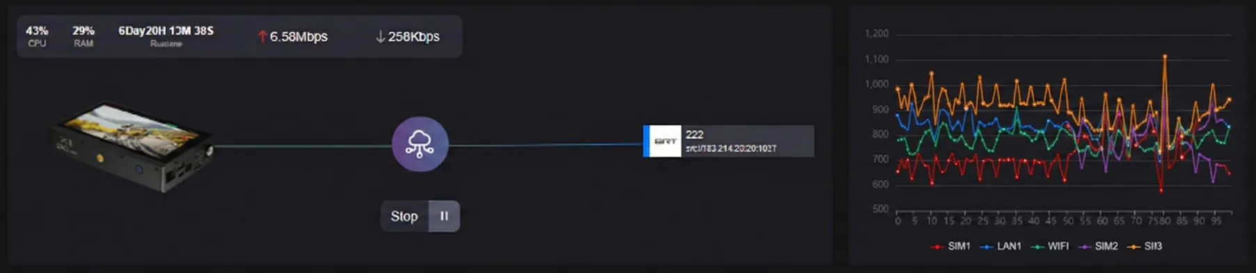
- System Stats: Monitors CPU and RAM usage, along with total device Runtime.
- Traffic Monitor: Real-time Upload and Download speeds.
- Flow Topology: A visual diagram showing the data path from the X1 Device → Cloud/Bonding Server → Output Destinations (e.g., SRT, RTMP).
- Speed Graph: A scrolling line chart on the bottom right visualizes network stability over time, helping to identify jitter or bandwidth drops.
4.2 Encoding
Section titled “4.2 Encoding”The Encoding tab is where you configure the core video and audio compression parameters.
Video Signal Selection
Select the physical interface to be used as the video source: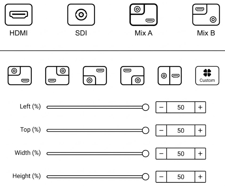
- Source Switch: Click either the HDMI or SDI icon to activate that input.
- Apply: You must click the red Apply button for the switch to take effect.
Main Stream Configuration
Configure the primary video stream sent to your streaming platforms and NDI receivers.Try it yourself You can click on the options below to view all available settings.
MJPEG Stream
This configuration directly controls the image refresh rate for the Web Preview and the remote preview thumbnail on the CNDLive Manager platform. The MJPEG stream generates a sequence of snapshots for low-bandwidth monitoring without consuming your primary video encoding resources.
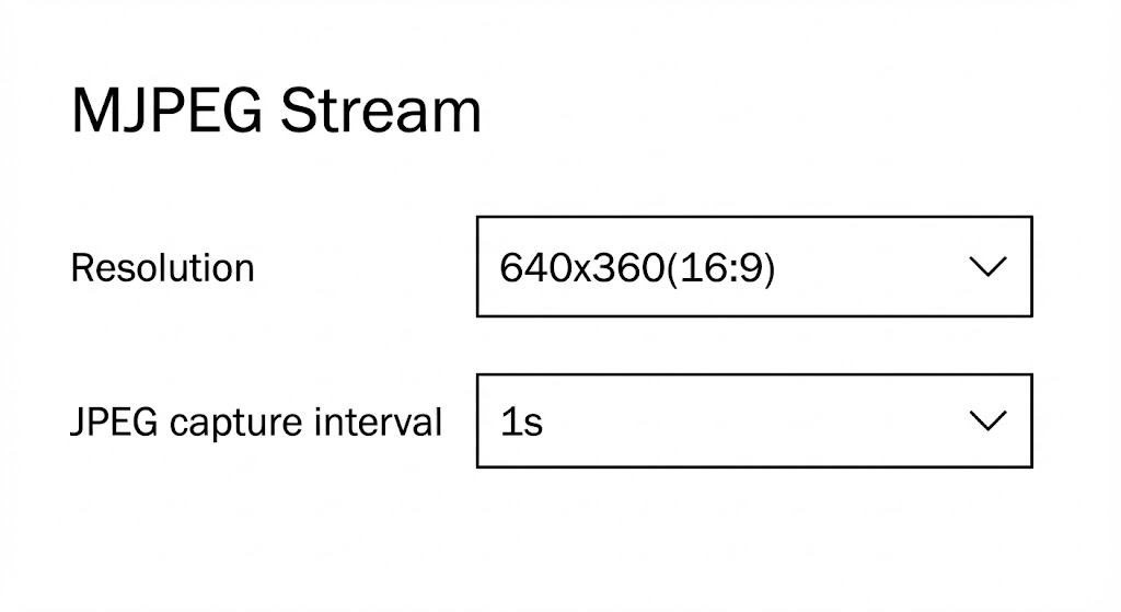 *
Resolution: Currently fixed at 640x360. This specific resolution is
locked to ensure maximum system stability and prevents management traffic from
interfering with your main video broadcast. * JPEG Capture Interval:
Determines how frequently a snapshot frame is refreshed. A shorter interval
provides a smoother preview but uses slightly more system resources. *
Selection: Choose from standard presets (1s, 2s, 3s) via the
dropdown menu. * Custom: Select “Custom” to input a specific integer. Note
that the value must be less than 10s.
*
Resolution: Currently fixed at 640x360. This specific resolution is
locked to ensure maximum system stability and prevents management traffic from
interfering with your main video broadcast. * JPEG Capture Interval:
Determines how frequently a snapshot frame is refreshed. A shorter interval
provides a smoother preview but uses slightly more system resources. *
Selection: Choose from standard presets (1s, 2s, 3s) via the
dropdown menu. * Custom: Select “Custom” to input a specific integer. Note
that the value must be less than 10s.
Audio Configuration
The X1 features a professional audio engine supporting up to 8 channels of encoding with matrix mapping capabilities.Try it yourself You can click on the options below to view all available settings.
Audio Source
Audio Matrix Mapping
For advanced audio routing, click the Mixer Icon next to the volume slider to open the Matrix Mapping tool.This allows you to map specific physical input channels to specific encoding output channels:
- Encoding Column: Represents the final audio channels in the stream (Ch1 - Ch8).
- Source Column: Select which physical input (e.g., Source Ch1, Source Ch2) feeds into that encoding channel.
- Mute: You can individually mute specific output channels within the matrix.
4.3 Advanced Settings
Section titled “4.3 Advanced Settings”The Advanced menu is designed for granular control over your production workflow. Beyond visual customization, it provides critical transmission utilities, allowing you to:
- Configure Stream Solo for independent, non-bonded network transmission.
- Customize video signal parameters (Color, ROI).
- Manage OSD (On-Screen Display) overlays for branding.
- Configure physical Shortcut Keys and LCD Screen brightness.
4.3.1 Stream Solo (Single Link)
Section titled “4.3.1 Stream Solo (Single Link)”The Stream Solo mode bypasses the bonding server entirely. Instead of aggregating bandwidth, it intelligently selects the single best available physical connection to push your stream. This mode is ideal for environments with a dedicated, high-speed fiber connection, or as a strategic backup line.
Network Priority Logic
When “Stream Solo” is enabled, the X1 does not use all connections simultaneously. It scans for internet connectivity based on a strict hardware priority queue. It will always use the highest-priority active connection and ignore the others.Transmission Priority Chain
→ | → |
*If the Wired connection is unplugged, the device instantly switches to Wi-Fi. If Wi-Fi drops, it fails over to SIM 1.
Stream Solo supports a wide range of standard IP protocols suitable for different receiving ends:
- RTMP/RTMPS: The industry standard for pushing to CDNs like YouTube Live, Twitch, and Facebook Live.
- SRT(Caller/Listener): Best for point-to-point transmission over the public internet. It provides low latency and packet loss recovery (ARQ).
- RTSP: Real-Time Streaming Protocol. Often used for local surveillance systems or pulling the stream into VLC player on the same LAN.
- UDP/RTP (Unicast/Multicast): Lightweight protocols used primarily for local IPTV networks where latency is critical and network stability is guaranteed.
Video Source Selection: Before applying any effects (Cropping, Rotation, etc.), you must first select the target input source (HDMI or SDI) at the top of the panel. Settings are independent for each source.
4.3.2 Cropping
Section titled “4.3.2 Cropping”The Cropping function allows you to define a specific region of interest (ROI) from your video source, removing unwanted borders or focusing on a specific area to meet different scene requirements.
- Enable/Disable: Toggle the Cropping switch to activate or deactivate the feature.
- Visual Preview: A graphical representation shows the cropped area (inner lighter box) relative to the full video frame.
Parameter Configuration You can adjust the cropping area using the sliders, by clicking the + / - buttons, or by entering specific percentage values:
Try it yourself Drag the sliders or input values below to simulate the cropping behavior.
Left (%): Adjusts the horizontal starting position from the left edge (Range: 0% - 100%).
Top (%): Adjusts the vertical starting position from the top edge (Range: 0% - 100%).
Width (%): Defines the width of the visible screen area (Range: 0% - 100%).
Height (%): Defines the height of the visible screen area (Range: 0% - 100%).
4.3.2 Rotation/Flip
Section titled “4.3.2 Rotation/Flip”The Rotation and Flip functions allow you to correct the video orientation digitally. This is essential for scenarios where the camera is mounted upside down (ceiling mount), used in portrait mode (mobile streaming), or requires image mirroring.
Try it yourself Change the settings below to see how Rotation and Flip affect the video output.
Rotation: Rotates the entire video frame in a clockwise direction.
- 0° Rotation: Keeps the original landscape orientation.
- 90° Rotation: Rotates 90 degrees clockwise (Suitable for vertical screens).
- 180° Rotation: Rotates 180 degrees (Suitable for inverted cameras).
- 270° Rotation: Rotates 270 degrees clockwise.
Flip: Mirrors the video image along a specific axis.
- No Flip: Keeps the original image state.
- Flip Horizontally: Mirrors the image left-to-right (often used for teleprompters or “selfie” mode).
- Flip Vertically: Mirrors the image top-to-bottom.
- Flip horizontally and vertically: Mirrors along both axes simultaneously.
4.3.3 No Signal Background
Section titled “4.3.3 No Signal Background”This feature defines the default display output when the device fails to detect a valid video signal or when the source is disconnected.
- Color Options: Select from 6 preset solid colors to fill the screen during signal loss.
- Available Colors: Black, Red, Green, Blue, Cyan, Purple.
- Configuration: Click on a color block to select it, then click Apply to save the setting.
4.4.4 OSD Management
Section titled “4.4.4 OSD Management”The OSD (On-Screen Display) feature allows you to superimpose dynamic information or branding onto your video streams, such as Logos, Time/Date stamps, or text.
To use an image overlay (e.g., a station logo), you must first upload the file to the device’s local library.
- Upload: Click the Image Placeholder under “Overlay Setting” to open the upload dialog.
- Requirements:
- Format: Supports JPG, JPEG, and PNG.
- Size: File size must be below 5MB.
- Management: Once uploaded, images appear in the gallery and can be selected for overlays.
Try it yourself Select a content type (Text/Date/Image) and click the grid to position it on the screen.
content Configuration
Depending on the selected type, configure the specific display parameters: * Text: Enter your custom text in the “Overlay Text” field. * Date/Time: Select from preset formats (e.g.,YYYY/MM/DD hh:mm:ss) to display the
real-time system clock. * Image: Select a previously uploaded logo from the
visual list.
Styling (Text/Date/Time)
* Text Color: Click the color box to pick a font color. * Font Size: Select a size from the dropdown menu (Range: 12 to 72) to ensure readability on different screens.OSD List Management
The OSD List at the bottom shows all active overlays. * Status: View the current state (e.g., “Success”). * Manage: Use the Edit (Gear icon) to modify settings or Delete (Trash icon) to remove an overlay. * Batch Deletion: Use the checkbox to select multiple items and click Batch Deletion for quick cleanup.4.4.5 Shortcut Key
Section titled “4.4.5 Shortcut Key”The Shortcut Key feature allows you to define custom hotkeys for frequently used operations, enabling instant control without navigating through menu layers.
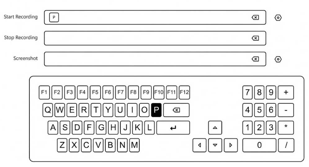
Supported Functions
You can assign unique shortcuts to the following critical actions: * Start Recording: Triggers the onboard recording immediately. * Stop Recording: Ends the current recording session. * Screenshot: Captures a still image of the current video feed.Configuration Steps
- Select Function: Click the input field next to the desired function (e.g., “Start Recording”). 2. Assign Key: A virtual keyboard will appear at the bottom of the screen. Click any key (Letters, Numbers, or F1-F12) to assign it. * Example: In the diagram, the key “P” is assigned to Start Recording. 3. Clear/Delete: Click the ❌ inside the input field.
4.4.6 Screen
Section titled “4.4.6 Screen”The Screen settings allow you to optimize the 5.5-inch touch display for different lighting conditions and mounting orientations.
Brightness Adjustment
Control the backlight intensity of the LCD screen.- Range: 0 - 100. * Recommendation: * Indoor: Set to 30 - 50 to save battery life. * Outdoor: Set to 80 - 100 for maximum visibility under direct sunlight.
Screen Rotation
This feature is essential for complex camera rigging. If the X1 is mounted upside down on a camera arm or a rack, you can flip the UI for proper viewing.Quick Access: LCD Control Center
You don’t always need to log in to the Web UI to change these settings. The X1 features a smartphone-style Control Center for on-the-fly adjustments.4.4.7 Heat Dissipation
Section titled “4.4.7 Heat Dissipation”Video encoding and network bonding are computationally intensive tasks that generate heat. The X1 features an intelligent active cooling system to ensure stability under various operating conditions. This section allows you to manage the fan strategy based on your environment.
Fan Control Modes
You can select the fan operation mode from the dropdown menu to balance cooling performance with acoustic noise levels.
-
Auto (Recommended)
- Logic: The system automatically adjusts fan speed in real-time based on the internal CPU temperature.
- Use Case: Suitable for 90% of scenarios. It keeps the device quiet when idle and ramps up cooling during heavy 4K encoding.
-
High Performance (Turbo)
- Logic: The fan runs at maximum speed (100%) continuously, regardless of the current temperature.
- Use Case: Critical for outdoor broadcasts in direct sunlight, high-temperature environments (>30°C / 86°F), or when the device is placed inside a backpack with limited airflow.
- Note: This mode produces audible fan noise.
-
Quiet Mode
- Logic: The fan runs at the lowest possible speed to minimize noise interference.
- Behavior: The fan speed will NOT increase automatically, even if the device temperature rises during operation.
- Use Case: Ideal for quiet indoor interviews or studio settings where the microphone is close to the encoder.
5.5 Recording
Section titled “5.5 Recording”The Recording module allows you to store high-definition video directly to a local USB drive or TF (Micro SD) card. It supports continuous loop recording and file segmentation, ensuring you never miss a critical moment.
5.5.1 Recording Settings
Section titled “5.5.1 Recording Settings”Configure how the video files are saved, named, and managed.
- Record Switch: Toggle this switch to Enable or Disable the recording function.
- Storage Device: Select the target destination (e.g., USB drive or TF card) from the dropdown list.
- Recording Format: Choose the container format for the video files.
- ts: Transport Stream. Highly recommended for live production because the file remains readable even if power is lost suddenly.
- mp4 / mkv: Standard formats for broad compatibility with media players.
- Naming Convention:
- Prefix: Custom text added to the beginning of the filename (Default:
REC-). - Folder Name: The directory where files will be stored (Default:
RECORDING).
- Prefix: Custom text added to the beginning of the filename (Default:
- Max Duration: Defines how the system splits long recordings into smaller, manageable files.
- Options: 10min, 30min, or One Hour.
- Benefit: Splitting files prevents data loss if a single large file becomes corrupted.
- Strategy: Defines behavior when the storage becomes full.
- Loop: Circular recording. The system automatically deletes the oldest files to make room for new ones. Ideal for 24/7 monitoring.
- Stop when full: Recording stops immediately when storage capacity is reached. Recommended for archiving critical events where old footage must not be lost.
5.5.2 Storage Management
Section titled “5.5.2 Storage Management”This section provides tools to manage the physical storage media and the recorded files.
Disk Tools
* Status Bar: A visual progress bar showing Used vs. Total capacity (e.g.,6.3G / 115G). * Speed Test: Click to verify if the
disk’s write speed meets the bitrate requirements of your recording settings. *
Format: Erases ALL data on the drive and re-initializes the file system.
Use with caution!
Recording List
Displays a chronological list of all video files stored on the drive. * File Details: View Filename, Start/End Time, and File Size. * Management: * Delete: Click the Trash icon to remove individual files. * Batch Deletion: Check multiple boxes on the left and click Batch Deletion at the bottom to remove files in bulk. ---5.5 Network Settings
Section titled “5.5 Network Settings”The Network module manages the device’s connectivity interfaces. You can configure cellular (SIM), wired (LAN), and wireless (Wi-Fi) connections, as well as enable SNMP for remote monitoring systems.
5.5.1 Wired Network
Section titled “5.5.1 Wired Network”Configure the IP address for the Ethernet interface.
- DHCP Switch: Toggle ON to automatically acquire an IP address from your router/switch. Toggle OFF to manually configure a Static IP.
- Interface Status: Displays current connection state (e.g., “Connected”).
- Manual Configuration: When DHCP is OFF, you must manually input:
- IP Address / Subnet Mask: Ensure these match your local network segment.
- Gateway: The router’s IP address.
- DNS 1 / DNS 2: Domain Name Servers for internet access.
- Apply: Click to save changes. Note: Changing IP settings may disconnect the Web UI momentarily.
5.5.2 Wireless Network (Wi-Fi)
Section titled “5.5.2 Wireless Network (Wi-Fi)”Connect the device to a wireless hotspot.
Connection Management
* Wi-Fi Switch: Toggle ON to enable the wireless module and scan for available networks. * Network List: Displays available SSIDs, Signal Strength, and Connection State. * Connect: Click “Connect” next to a network, enter the password, and confirm. * Forget Password: Removes saved credentials for a connected network. * Refresh List: Rescans the environment for new hotspots.Manual Addition (Hidden SSIDs)
For networks that do not broadcast their SSID, use the + Add Another Network button. * SSID: Enter the exact network name manually. * Encryption Type: Select the security protocol (e.g., WPA, WEP, or None). * Password: Enter the security key.5.5.3 Cellular Settings (4G Modules)
Section titled “5.5.3 Cellular Settings (4G Modules)”The X1 is designed for mission-critical mobile broadcasting. Each cellular module is paired with professional-grade SIM slots to ensure connectivity in the most challenging network environments.
Dual-SIM Slot Logic
Each cellular module on the X1 features a Dual-SIM card slot design.
- Redundancy: You can insert two different SIM cards into a single module (e.g., SIM 1 and SIM 2).
- Switching: While only one SIM per module can be active at a time, you can easily switch between them via the Web UI or LCD screen. This is ideal for crossing borders or switching to a secondary carrier if the primary one has poor signal.
The Modem List provides real-time telemetry. You may be required to provide the values of those parameters when participating in similar radio registration processes
| Parameter | Description |
|---|---|
| Index | Identifies the physical slot (e.g., Modem 1, Modem 2). |
| Net Mode | The network generation currently in use: • LTE: 4G connection (High Speed). • WCDMA/HSPA: 3G connection (Fallback, lower speed). |
| Operator | The ISP Name (Carrier) read from the SIM card. |
| Signal (dBm) | Received Signal Strength Indicator. The closer to 100, the stronger the signal. |
| IP Address | The WAN IP assigned by the carrier. Note: Most 4G networks assign a private IP (NAT), meaning the device is not directly accessible from the public internet. |
| IMEI | International Mobile Equipment Identity. The unique hardware fingerprint of the 4G module itself. Usage: Required when registering the device on “whitelist-only” networks (e.g., Verizon Enterprise). |
| IMSI | International Mobile Subscriber Identity. The unique user ID within the cellular network. Usage: Carriers use this to authenticate your subscription on their backend. |
| ICCID | Integrated Circuit Card Identifier. The unique serial number printed on the back of your physical SIM card. Usage: Check this to confirm which specific SIM card is currently inserted in the slot. |
Regional Version Identification
To ensure optimal performance across global LTE/4G frequency bands, the X1 is released in specific regional versions. You can identify your device’s optimized region by checking the last two letters of the Serial Number (S/N) found on the device label or the “System Info” page. For example, EU stands for Europe, and US stands for North America.
- APN Settings: By default, the X1 uses an “Auto APN” database. For private APNs or specialized IoT cards, toggle to Manual to enter the specific APN name, username, and password.
- Network Mode: You can force the modem to 4G Only to prevent the device from “ping-ponging” between unstable signal types in congested areas.
- Data Roaming: Must be enabled if you are using an international roaming SIM card.
5.5.4 SNMP
Section titled “5.5.4 SNMP”Enable Simple Network Management Protocol (SNMP) for integration with centralized monitoring systems.
- SNMP Switch: Toggle ON to activate the agent.
- Port: Default is 161. Change this only if your network policy requires a custom port.
- Community: The authentication string (similar to a password). Default is
public.
5.7 Settings
Section titled “5.7 Settings”The Settings menu allows you to manage system-level configurations, including user accounts, time synchronization, security, and logs.
5.7.1 User Management
Section titled “5.7.1 User Management”This section allows you to manage access credentials for the device. You can create multiple user accounts to secure the device settings.
Adding a User
To create a new account, follow these steps: 1. Click the + Add User button at the top right corner. 2. In the pop-up window, fill in the required fields: * User Name: The login ID for the new user. * Remark: A label or description (e.g., “Staff”, “IT”). * Password: Set a secure login password. 3. Click Apply to save the new user.Managing Users
The User List displays all current accounts. You can perform the following actions:- Edit: Click the Gear Icon to modify the user’s remark or reset their password.
- Delete: Click the Trash Icon to remove a user account permanently. * Note: The default admin account cannot be deleted, only edited.
5.7.2 Time and Zone
Section titled “5.7.2 Time and Zone”Ensuring the device runs on the correct time is essential for accurate log recording, troubleshooting, and task scheduling.
Time Configuration
Select one of the three available Modes to synchronize the system clock:- Timing with current PC: Instantly syncs the device’s time with the computer you are currently using to access the Web UI. This is the quickest method for initial setup.
- Manual Timing: Allows you to manually input a specific date and time string (Format:
YYYY-MM-DD HH:MM:SS). This is useful for isolated networks without internet access. - Sync from NTP Server: Connects to a Network Time Protocol server for high-precision, automatic synchronization.
- Setting: You must enter a valid NTP Server Address (e.g.,
pool.ntp.org). Supports multiple addresses separated by spaces.
- Setting: You must enter a valid NTP Server Address (e.g.,
Zone Configuration
Define the geographical region to ensure the offset from UTC is correct.- Region and Position: Click the dropdown menu to select your time zone. The list supports selection by: _ Major Cities: e.g., “Asia/Shanghai”, “Seoul”, “New York”. _ GMT Offsets: e.g., “GMT-8”, “GMT+1”.
5.7.3 System
Section titled “5.7.3 System”The System panel is the hub for device maintenance. Here you can view hardware details, perform firmware upgrades, reset configurations, or restart the device.
Device Info
Displays critical identity information for the device: * Versions: View current Hardware and Software versions to determine if an update is needed. * Serial Number: Click the ❐ to quickly copy the SN to your clipboard (Essential information for connecting to CNDLive Manager and technical support). * Device Name: Click the ✏️ to rename the device. This name identifies the unit on the network and in the NDI discovery list.Firmware Update
Keep your device running efficiently by installing the latest software. 1. Select File: Click to browse your local computer for the update file. * Requirement: The file must be in .bin format. 2. Update: Once the filename appears, click the Update button to begin. * Warning: Do not disconnect power during the update process to prevent system corruption.Reset Factory Settings
This operation restores the device to its original out-of-the-box state. * Action: Click Reset to wipe all custom configurations (Network IP, Encoding params, User accounts, etc.). * Result: The device will revert to default settings and automatically reboot.Reboot
Performs a safe software restart of the device. * Action: Click Reboot to restart the system without losing your saved configurations. * Duration: The process typically takes about 30 seconds.5.7.4 Security
Section titled “5.7.4 Security”The Security settings allow you to configure the network protocols used to access the device’s Web User Interface, ensuring secure data transmission.
HTTP/HTTPS Setting
Configure the ports and protocols for web access: * HTTP: Standard web traffic. * Checkbox: Check to enable HTTP access (Default: Enabled). * Port: Default is 80. You can customize this if port 80 is blocked or used by other services. * HTTPS: Encrypted web traffic (Recommended for public network access). * Checkbox: Check to enable HTTPS access. * Port: Default is 443.Certificate Management
To use HTTPS securely without browser warnings, you must upload valid SSL certificates. * CA Certificate: Drag and drop your certificate file here. * Format Requirement: Supports .crt files. * CA Secret Key: Drag and drop the corresponding private key file here. * Format Requirement: Supports .key files.5.7.5 Log
Section titled “5.7.5 Log”The Log system records key operational events, system errors, and warning messages. This is the first place to check if you encounter unexpected behavior or need to troubleshoot connectivity issues.
Log Viewing & Filtering
The main dashboard displays a chronological list of system events. You can filter the view to focus on specific types of messages: * Filters: Use the checkboxes at the top right to toggle All, Information, Warning, or Error logs. * Event Types: * Information 💬 : General system activities, such as “Wi-Fi connected successfully” or “Settings updated”. * Warning ⚠️ : Alerts that don’t stop operation but require attention, such as “Device is updating”. * Error ❗ : Critical failures, such as “HDMI Signal Lost” or connection drops.Log Management
Use the control buttons at the bottom right to manage the log history:- Export: Downloads the current log history to your computer for offline analysis or technical support.
- Format: The file is saved as an HTML document (e.g.,
Log_2026_01_16_14_03_56.html) which can be viewed in any web browser.
- Format: The file is saved as an HTML document (e.g.,
- Clear: Click the 🗑️ icon to permanently delete all currently recorded events from the device memory.
6. Troubleshooting
Section titled “6. Troubleshooting”Q: The screen shows a blue “No Signal” image.
A: Check your physical cable connections. Then, verify that the Input Source setting (HDMI vs. SDI) in the Control Center matches your connection.
Q: Streaming is laggy or buffering.
A: Check the Traffic Graph on the LCD Advanced view.
- Is your total Upload Speed higher than your Encoding Bitrate?
- Are multiple 4G links active? If not, check SIM cards and APN settings.
- Try switching bitrate control to CBR and lowering the bitrate (e.g., to 3000 Kbps).
Q: I cannot login to the Web Page.
A: Ensure your computer is on the same network segment as the X1. If connecting directly via Ethernet cable, set your computer’s IP to a static address in the same range (e.g., 192.168.0.100).
Q: Audio is out of sync.
A: Go to Encoding > Audio in the Web UI. Use the Audio Offset slider to add delay (+/- ms) until the audio matches the video.