D1 Decoder User Manual
Welcome to the D1 Decoder manual. If encoders are designed to push your content to the world, the D1 Decoder is designed to pull it back. It reliably catches your IP streams from anywhere and converts them back into pristine, uncompressed baseband video for your switchers and monitors.
1.1 Product Overview
Section titled “1.1 Product Overview”The CNDLive D1 4K HDMI/3G-SDI Decoder is a professional-grade hardware decoding appliance. It is engineered to pull various network video streams and seamlessly convert them into standard physical video signals in real-time.
IP Streams
SRT / RTMP / NDI / RTSP / UDP / HLS
D1 Decoder
Baseband
4K HDMI / 3G-SDI
Core Capabilities
- Multi-Protocol Support: Effortlessly pulls streams via SRT, RTMP, RTSP, UDP, HTTP, HLS, and NDI|HX.
- 4K Ultra HD Output: The HDMI port supports up to 4K 60fps output, delivering crystal-clear quality for monitoring.
- Broadcast Standard SDI: The 3G-SDI port ensures seamless integration with professional video switchers and matrices.
- Image Scaling (Cross-Conversion): Built-in hardware processing allows you to force a specific output resolution and framerate, regardless of the incoming stream’s format.
1.2 Technical Specifications
Section titled “1.2 Technical Specifications”| Feature | Specification |
|---|---|
| Video Outputs | 1x HDMI 2.0 (Up to 3840x2160P 60Hz) 1x 3G-SDI (Up to 1920x1080P 60Hz) |
| Audio Interface | 1x 3.5mm Line Out (Stereo) |
| Network | 2x Gigabit Ethernet (1000M) LAN 1 supports PoE |
| USB Interfaces | 1x USB 3.0 Type-A, 1x USB Type-C |
| Power | DC 12V / 2A or PoE |
| Recording | Supports USB storage (TS, MP4, MKV) |
1.3 Package Contents
Section titled “1.3 Package Contents”- 1x D1 Host Unit
- 1x Power Adapter
- 1x Warranty Card
- 1x Quick Start Guide
- 1x Quality Certificate
2. Hardware Interfaces
Section titled “2. Hardware Interfaces”2.1 Front Panel
Section titled “2.1 Front Panel”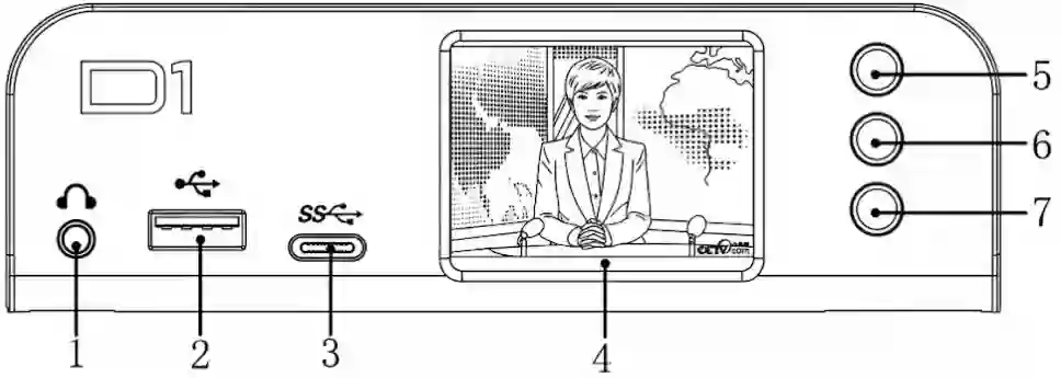
- Line Out: 3.5mm analog audio jack. Connect headphones to monitor the decoded audio.
- USB 3.0: Connect a USB drive for local recording or firmware updates.
- Type-C: For peripheral expansion (e.g., USB Headsets for future intercom features) or storage.
- LCD Screen: Displays video preview, IP address, and system menus.
- Up: Scroll up / Return.
- Confirm: Enter menu / Confirm selection.
- Down: Scroll down / Next page.
2.2 Rear Panel
Section titled “2.2 Rear Panel”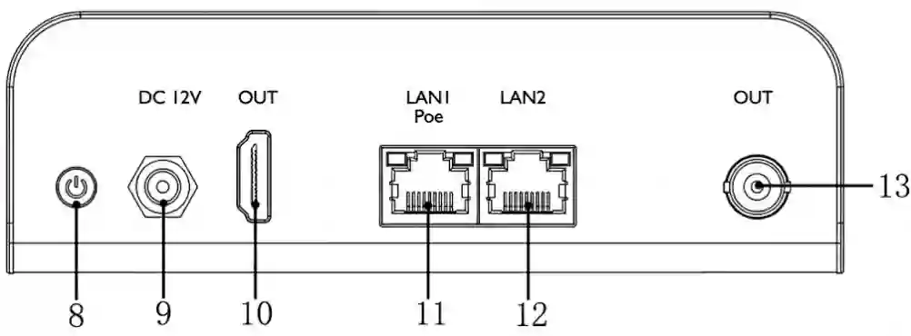
- Power Button: Press to turn the device On/Off.
- DC 12V: Input for the provided power adapter.
- HDMI OUT: Connect to a TV, Monitor, or Projector.
- LAN 1 (PoE): Primary Network Port. Supports Power over Ethernet.
- LAN 2: Secondary Network Port (for dual-network setups).
- SDI OUT: Connect to professional video switchers or broadcast monitors.
3: Installation & Connection
Section titled “3: Installation & Connection”Proper physical installation is the foundation of a stable decoding workflow. The D1 Decoder is designed for quick deployment in both permanent studio racks and temporary field environments.
3.1 Unpacking and Preparation
Section titled “3.1 Unpacking and Preparation”Before starting the installation, inspect the equipment for any physical damage that may have occurred during shipping. Ensure you have the following necessary cables ready:
- A standard Cat5e / Cat6 Ethernet cable for network access.
- A high-quality HDMI 2.0 cable (for 4K display) or a 75Ω BNC coaxial cable (for 3G-SDI output).
- The provided 12V DC Power Adapter (if not using PoE).
3.2 Network and Power Connection
Section titled “3.2 Network and Power Connection”The D1 Decoder features a flexible power design to suit different deployment scenarios.
Option A: PoE (Power over Ethernet) - Recommended
If your network switch supports PoE (802.3af/at), you can power the D1 and provide it with network data using a single Ethernet cable.- Connect one end of the Ethernet cable to your PoE switch.
- Connect the other end to the LAN / PoE port on the back of the D1.
Option B: Standard DC Power
- Connect the standard network cable to the LAN port.
- Plug the provided 12V DC power adapter into the DC IN port and tighten the threaded locking ring to prevent accidental disconnection.
3.3 Video Output Connection
Section titled “3.3 Video Output Connection”This is where the decoded IP stream is converted back into a physical video signal. You can use HDMI, SDI, or both simultaneously.
- HDMI Connection: Connect the HDMI OUT port to a monitor, TV, or projector. This is ideal for multi-view monitoring or digital signage.
- SDI Connection: Connect the SDI OUT port to a professional video switcher (e.g., vMix, ATEM), a video matrix, or a broadcast monitor.
3.4 Audio Output (Optional)
Section titled “3.4 Audio Output (Optional)”By default, the decoded audio is embedded within the HDMI and SDI signals. However, if you need to route the audio separately:
- Connect a 3.5mm audio cable from the AUDIO OUT port to your external audio mixer or active speakers.
3.5 Powering On
Section titled “3.5 Powering On”Once all connections are secure:
- Turn on the power switch located on the rear panel.
- The LCD screen will boot up.
- Check the network port LEDs: A solid or blinking green light indicates a successful network connection.
4. LCD Screen Operation
Section titled “4. LCD Screen Operation”The LCD screen allows you to check status and configure basic settings without a computer.
4.1 Navigation Controls
Section titled “4.1 Navigation Controls”The physical buttons located to the right of the screen are your primary control tools:
- UP / DOWN: Cycle through the main dashboard pages (System State -> Network1 -> Network2 -> Output).
- OK (Square Button):
- Short Press: Enter a sub-menu or confirm a selection (e.g., toggle a switch).
- Long Press: Triggers specific shortcuts (e.g., Factory Reset on startup).
4.2 System Status
Section titled “4.2 System Status”This is the root menu page, providing a comprehensive health check of the device.
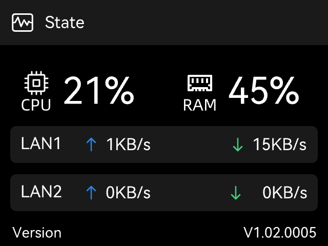
CPU / RAM: Shows current resource usage.
Network Traffic: Real-time uplink and downlink speeds for both Gigabit Ethernet ports
Version: Current firmware version.
4.3 System Maintenance Menu
Section titled “4.3 System Maintenance Menu”Pressing OK on the System Status page enters the critical maintenance menu:
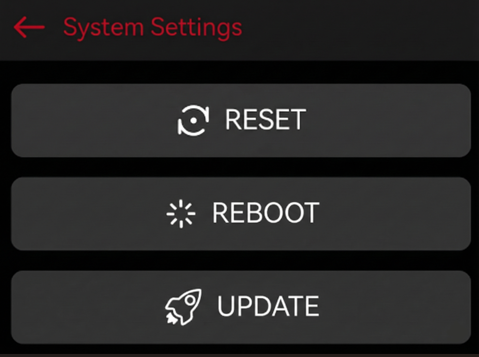
Reset: Restores factory settings. Use this if you are locked out of the device or facing configuration conflicts.
Reboot: Performs a safe soft restart of the system.
Update (via USB): Allows firmware upgrades without a network connection.
- Requirement: Insert a USB drive with the firmware (
.binfile) in the root directory before selecting this option.
4.4 Network Configuration
Section titled “4.4 Network Configuration”Press Down to navigate to Network settings. The D1 separates Wired Networkand 1/2 configurations.
Wired Network (LAN)
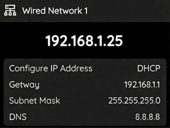
Info Display: Shows current IP Address, Gateway, Subnet Mask, and DNS.
Action (Press OK): Enters the Setting menu. You can select between two modes:
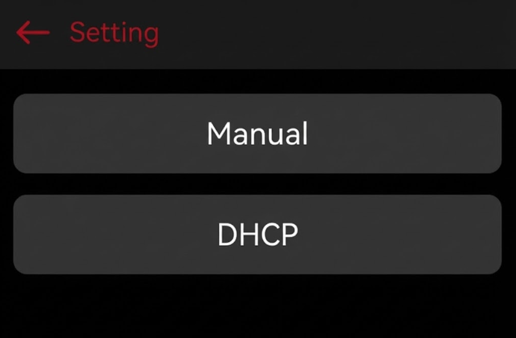
Manual: Select this to set a Static IP.
- You will enter a configuration screen to input the IP Address, Gateway, and Subnet Mask.
- A confirmation screen will appear (e.g.,
192.168.1.25). You can press the Up/Down buttons to adjust the numeric values. Select Confirm to save the changes. DHCP: Select this to automatically acquire an IP address from your network server.
4.5 Output Status
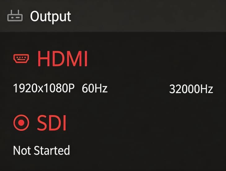
Section titled “4.5 Output Status”Use the Down button to scroll until you highlight the Output page.The screen will instantly display the real-time telemetry of your physical connections.
| On-Screen Item | Status Meaning | Professional Interpretation |
|---|---|---|
| HDMI | 3840x2160P60 (Example) | Connected. The port is successfully outputting a 4K 60fps signal to the connected display. |
Not Start | No Link. The HDMI cable is unplugged, or the receiving monitor is powered off/unresponsive. | |
| SDI | 1920x1080P50 (Example) | Connected. The 3G-SDI port is actively sending a 1080p 50fps signal to your switcher or matrix. |
Not Start | No Link. The BNC cable is unplugged, or there is a break in the cable run. |
5. Web Management UI
Section titled “5. Web Management UI”The Web UI is the primary control center for the D1 Decoder.
5.1 Login
Section titled “5.1 Login”- Connect a computer to the same network as the D1 Decoder.
- Find the IP Address on the D1’s LCD screen (Network page).
- Open a web browser (Chrome recommended) and enter the IP address.
- Login with the default credentials:
- Username:
admin - Password:
admin
- Username:
5.2 Dashboard Overview
Section titled “5.2 Dashboard Overview”The main interface allows you to manage video sources and outputs.
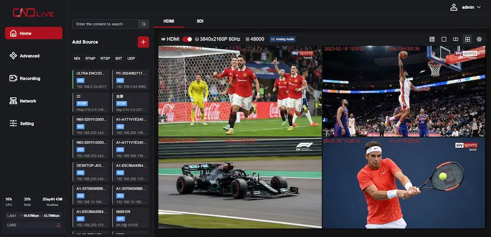
5.2.1 Adding Network Stream
Section titled “5.2.1 Adding Network Stream”To tell the D1 what to decode, click the Add button in the channel list. A configuration window will appear where you need to define the stream parameters. The D1 supports a massive array of IP protocols. Here is how to configure the most commonly used broadcast standards:
SRT (Secure Reliable Transport)
SRT is the industry standard for point-to-point transmission over the public internet. It offers pristine quality and robust packet loss recovery.- Mode:
- Caller: The D1 actively connects to a remote server or encoder. You must input the remote IP Address and Port.
- Listener: The D1 waits passively for an encoder to connect to it. You only need to define a local Port (e.g.,
9000). (Note: The D1 must have a public static IP or port forwarding enabled on your router for this to work).
- Latency (ms): The decoding buffer.
- Expert Advice: Set this to 3 to 4 times the RTT (Round Trip Time) between the encoder and decoder. If the network is unstable, increasing this value (e.g., to 500ms or 1000ms) will prevent dropped frames, at the cost of higher delay.
RTMP / HTTP / HLS
Used for pulling streams from traditional CDN platforms, cloud servers, or media centers.- Stream URL: Simply paste the full pull address provided by your platform (e.g.,
rtmp://live.example.com/app/streamkey).
RTMP Server (Host Mode)
Unlike standard RTMP which pulls a stream from the cloud, the RTMP Server mode turns the D1 Decoder into a local host. This allows encoders (like OBS Studio, vMix, or a smartphone app) to push their streams directly to the decoder over the local network.- Port: The listening port (default is usually
1935). - App Name: The application directory (e.g.,
live). - Stream Name: Your customized stream key (e.g.,
ch1).
💡How to configure your Encoder (e.g., OBS): Based on the settings above, you would configure your pushing software to target the D1’s IP address:
- Server / URL:
rtmp://<D1_IP_Address>:1935/live - Stream Key:
ch1
RTSP / UDP (Local Network)
Ideal for local IPTV networks, IP security cameras, or campus broadcasts.- URL Format: Input the standard URI (e.g.,
rtsp://192.168.1.100:554/live/ch1). - Protocol Type (RTSP): Choose between TCP (better for traversing strict corporate firewalls) or UDP (lower latency).
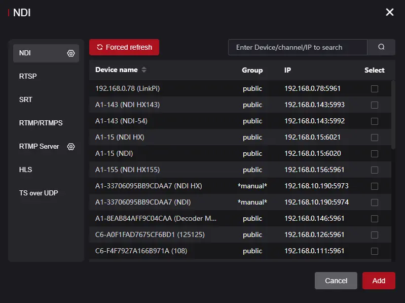
NDI
For local production workflows, NDI is practically plug-and-play.- Discovery: The D1 will automatically scan the local area network for available NDI sources. Simply select the desired source from the generated dropdown list.
OMT
OMT is a next-generation, open-source protocol designed for high-performance, ultra-low latency video transmission over a Local Area Network (LAN). It serves as a royalty-free alternative to proprietary formats like NDI.- Discovery: Similar to NDI, the D1 will automatically scan the local network for active OMT senders (such as vMix or OBS with the OMT plugin). Select your target source from the generated list.
Network Buffer (Jitter Buffer)
If you are pulling streams over a highly congested network, increasing the network buffer will pre-load more video data into memory. This ensures smooth baseband output even if the network speed momentarily drops to zero.The Encoder-Decoder Pair
If you are using an C6 Encoder in the field and a D1 Decoder in your studio, the most robust, zero-cloud-cost setup is:
1. Configure the D1 Decoder as an SRT Listener on Port 9000.
2. Configure your studio’s main router to forward Port 9000 to the D1’s local IP address.
3. Configure the c6 Encoder as an SRT Caller, pointing to your studio’s Public IP address.
Result: You have just created a direct, ultra-low latency broadcast tunnel across the globe!
5.2.2 To Start Decoding
Section titled “5.2.2 To Start Decoding”click
Camera 01
RTSP10.0.0.239
-
Method 1:Click to Select
- Click anywhere inside the Preview Window
- Click the desired source from the list
-
Method 2:Drag and drop
- Select a source from the list on the left.
- Drag and drop the source into the Preview Window.
5.2.3 Decoding Output Settings
Section titled “5.2.3 Decoding Output Settings”The Decoding Settings panel is your command center for routing the decoded network stream to your physical video outputs. The D1 Decoder treats the HDMI and SDI ports as two completely independent pipelines, allowing you to run different resolutions and audio layouts simultaneously.
Independent Interface Switching
At the top of the interface, you will see the HDMI and SDI tabs.
- Click on either tab to configure its specific output settings.
- Notice how the parameters (like resolution or audio channels) can be set entirely differently for each tab. This means you can output a full 4K signal to an HDMI monitor while simultaneously outputting a down-scaled 1080p signal to your SDI broadcast switcher.
Quick Status Bar
The main row of the configuration interface gives you an immediate overview of your current output parameters for the selected tab:
- Port Toggle Switch: The red/gray toggle allows you to quickly enable or disable the physical output for that specific port without stopping the entire decoding process.
- Resolution / Refresh Rate: Displays the currently active video output format (e.g.,
3840x2160P 60Hz). - Audio Sample Rate: Shows the current audio sampling standard (e.g.,
48000Hz). - Analog Audio Tag: Indicates if the physical 3.5mm analog audio jack is currently bound to this output port’s audio feed.
Audio Matrix Routing (Mixer Icon)
Click the Mixer Icon (the icon with vertical equalizer sliders) on the right side of the interface to open the Audio Matrix window.
The Audio Matrix allows you to map specific incoming IP audio channels to the specific physical output channels of the currently selected tab. It is strictly a mapping tool between the IP source and that specific physical interface.
- Use Case: Suppose the IP stream you are decoding contains multiple audio tracks (e.g., Source Ch 1/2 for English Program Audio, Source Ch 3/4 for Spanish translation). If you are configuring the HDMI output for the Spanish broadcast team, you can open the matrix and route Source Ch 3 to HDMI Left and Source Ch 4 to HDMI Right, while muting Ch 1/2. This allows you to precisely extract the required embedded audio tracks from the source and deliver them to your specific physical monitor or equipment.
Advanced Output Settings (Gear Icon)
Click the Gear Icon on the far right of the interface to access the deep configuration menu for the selected port.
In this advanced popup, you will configure critical parameters such as:
- Video Scaler Rules: Force a specific resolution and framerate to match your downstream switcher requirements.
- Color Space & RGB Range: Select between YUV or RGB color spaces.
- Expert Note: If you select RGB (specifically for HDMI), an additional RGB Range option will appear. You can choose Auto, Limited (16-235, standard for broadcast and TV monitors), or Full (0-255, standard for PC monitors). Matching this range correctly is essential to prevent “crushed blacks” or “washed-out” gray images.
- Audio Channels: Define the audio layout output for this interface (e.g., standard 2-channel stereo, or multi-channel if supported by your workflow).
- Audio Sampling: Set the audio sample rate (typically 48000 Hz for broadcast standards) to perfectly align with your production equipment’s master clock.
5.2.4 Web Preview Window
Section titled “5.2.4 Web Preview Window”The Preview Window is a powerful built-in tool that allows you to monitor the incoming IP stream directly within your web browser. This eliminates the need for third-party software (like VLC) just to verify if a stream is successfully reaching the D1 Decoder.
Interactive Controls
When viewing a stream, hover your mouse over the preview window to reveal the hidden control bar at the bottom.
- Info Button (“i” Icon): Toggling this button overlays a real-time telemetry panel in the upper-left corner.
- Pro-Tip: Use this to verify the true incoming Bitrate and Codec. If the bitrate is fluctuating wildly, you may have network issues on the pushing side.
- Record Button (Circle Icon): The D1 allows you to capture the incoming IP stream directly to its removable storage device.
- Clicking this starts recording the stream as a
.mp4or.tsfile. It is excellent for quick clipping or archiving without needing dedicated recording hardware.
- Clicking this starts recording the stream as a
- Custom Stream Name: The text displayed at the bottom center (e.g., ULTRA ENCODE) is the alias you assigned to this stream when you added it in the Channel setup. This helps you identify sources quickly when managing multiple feeds.
- Close Button (“X” Icon): Located in the top right, this stops the decoding.
5.3 Advanced
Section titled “5.3 Advanced”This section houses specialized tools designed to enhance your on-site monitoring, audio routing, and visual branding.
5.3.1 LCD Screen Preview
Section titled “5.3.1 LCD Screen Preview”In fast-paced broadcast environments or crowded server racks, the built-in 2-inch LCD screen provides a critical feature known as Confidence Monitoring. While compact, it allows you to visually confirm that your video stream is alive and healthy directly on the device without needing an external monitor.
Activation and Display Logic
Understanding how the LCD preview operates will help you monitor your streams efficiently:
- Pure Video Preview: Due to the compact 2-inch display size, the preview is designed to be highly focused and minimalist. It only displays the video frame and a small interface indicator.
- Interface Indicator: A prominent HDMI or SDI tag is displayed in the top-left corner of the screen, clearly indicating which physical interface’s video feed you are currently monitoring.
- Immediate Activation & Auto-Timeout: Once enabled in the settings, the LCD screen preview takes effect immediately. However, if you press any buttons on the front panel, the system will prioritize your manual operations and exit the preview. It will automatically return to the preview mode only after 30 seconds of inactivity.
- 3-Second Image Stream: To ensure 100% of the device’s processing power and memory bandwidth is dedicated to your actual broadcast, the LCD preview is not a full-motion video. Instead, it is rendered as an image sequence refreshing at 1 frame every 3 seconds.
5.3.2 Analog Audio Output Routing
Section titled “5.3.2 Analog Audio Output Routing”The D1 Decoder features a physical 3.5mm analog audio jack on its Front panel. This acts as a built-in hardware audio de-embedder, allowing you to extract digital audio from your IP stream and send it to analog equipment (like an audio mixer, active speakers, or a director’s headphones). Because the D1 can process HDMI and SDI pipelines completely independently, you must define which digital interface the analog jack should “listen” to.
Configuring the Analog Output
Navigate to Advanced -> Analog Audio in the Web UI. You will see a dropdown menu for Analog Audio Output with three distinct options:
- None: Mutes the physical 3.5mm jack completely. Choose this if you want to prevent accidental audio bleeding in a quiet studio environment.
- HDMI: The 3.5mm jack will perfectly mirror the audio currently being routed to the HDMI output.
- SDI: The 3.5mm jack will perfectly mirror the audio currently being routed to the 3G-SDI output.
5.3.3 OSD Management
Section titled “5.3.3 OSD Management”The OSD Management tab allows you to overlay custom graphics, text, and real-time clocks directly onto your decoded baseband video output. This is essential for adding station logos (watermarks), event timestamps, or internal monitoring labels before the signal reaches your displays or switchers.
The OSD interface is divided into two main sections: managing your image assets and configuring the active overlay rules.
Try it yourself Select a content type (Text/Date/Image) and click the grid to position it on the screen.
1. Overlay Setting (Image Library)
Before you can add an image watermark (like a company logo) to your video, you must first upload the image file to the decoder’s local storage.
- Click the Upload Icon (the square with an arrow) in the
Overlay Settingsection. - Select your image file from your computer.
2. Adding and Configuring OSD Elements
To create a new overlay rule, click the red + Add button on the right side of the OSD List. This will open the configuration popup.
You have granular control over what the overlay is and where it appears:
- Element Type: Choose from four dynamic options:
- Text: Input custom static text (e.g., “Director Multi-View” or “Cam 1”).
- Date / Time: Automatically generates a real-time running clock based on the device’s system time. Great for security monitoring or live event documentation.
- Image: Select a logo you previously uploaded in the Overlay Setting section.
- Target Interface (HDMI / SDI): Check the boxes to determine which physical output(s) will display this specific overlay.
- Position Grid: Use the intuitive 3x3 grid to instantly snap your overlay to the exact position you want (e.g., Top-Left, Bottom-Right, or Dead Center).
- Styling Options: If using Text, Date, or Time, you can customize the Overlay Text content, Text Color, and adjust the Font Size to ensure readability against different video backgrounds.
3. Managing the OSD List
Once you click Save, your rule will appear in the OSD List at the bottom of the main page. This list acts as your layers panel.
- Status Monitoring: Check the
Statecolumn (e.g., marked “success” in green) to verify the overlay is actively rendering. - Target Output: Quickly see if a rule is applied to HDMI, SDI, or both.
- Manage: Use the gear icon to re-edit an existing overlay’s position or text, or click the trash icon to delete it instantly. You can also use the Batch Deletion button to clear multiple overlays at once.
The “Clean Feed” Strategy
Because the D1 Decoder treats HDMI and SDI independently, you can create a highly professional workflow known as a “Clean Feed/Dirty Feed” split.
1. Create a logo watermark and target it only to the HDMI port (feeding the lobby or public display).
2. Leave the SDI target unchecked. The SDI port will output a pristine, graphic-free signal to your main production switcher for clean recording.
5.4 Recording
Section titled “5.4 Recording”Recordings can be stored directly to an external storage device plugged into the unit’s USB-A or USB-C host port. Supported devices include USB flash drives and portable SSDs. It supports continuous loop recording and file segmentation, ensuring you never miss a critical moment.
5.4.1 Recording Settings
Section titled “5.4.1 Recording Settings”Configure how the video files are saved, named, and managed.
- Record Switch: Toggle this switch to Enable or Disable the recording function.
- Storage Device: Select the target destination (e.g., USB drive or TF card) from the dropdown list.
- Recording Format: Choose the container format for the video files.
- ts: Transport Stream. Highly recommended for live production because the file remains readable even if power is lost suddenly.
- mp4 / mkv: Standard formats for broad compatibility with media players.
- Naming Convention:
- Prefix: Custom text added to the beginning of the filename (Default:
REC-). - Folder Name: The directory where files will be stored (Default:
RECORDING).
- Prefix: Custom text added to the beginning of the filename (Default:
- Max Duration: Defines how the system splits long recordings into smaller, manageable files.
- Options: 10min, 30min, or One Hour.
- Benefit: Splitting files prevents data loss if a single large file becomes corrupted.
- Strategy: Defines behavior when the storage becomes full.
- Loop: Circular recording. The system automatically deletes the oldest files to make room for new ones. Ideal for 24/7 monitoring.
- Stop when full: Recording stops immediately when storage capacity is reached. Recommended for archiving critical events where old footage must not be lost.
5.4.2 Storage Management
Section titled “5.4.2 Storage Management”This section provides tools to manage the physical storage media and the recorded files.
Disk Tools
- Status Bar: A visual progress bar showing Used vs. Total capacity (e.g.,
6.3G / 115G). - Speed Test: Click to verify if the disk’s write speed meets the bitrate requirements of your recording settings.
- Format: Erases ALL data on the drive and re-initializes the file system. Use with caution!
Recording List
Displays a chronological list of all video files stored on the drive.- File Details: View Filename, Start/End Time, and File Size.
- Management:
- Delete: Click the Trash icon to remove individual files.
- Batch Deletion: Check multiple boxes on the left and click Batch Deletion at the bottom to remove files in bulk.
5.5 Network Settings
Section titled “5.5 Network Settings”Stable network connectivity is the absolute foundation of any IP decoding workflow. The D1 Decoder is equipped with a professional Dual Gigabit Ethernet architecture, allowing you to physically separate your management network from your high-bandwidth streaming network.
5.5.1 Wired Network 1
Section titled “5.5.1 Wired Network 1”Ethernet 1 is the primary data port. It supports PoE (Power over Ethernet), meaning you can power the D1 and deliver data using a single cable connected to a PoE-enabled switch.
By default, Ethernet 1 is configured to seamlessly integrate into most standard network environments:
- DHCP Toggle: When turned ON (default), the decoder will automatically request an IP address, Gateway, and DNS from your router. This is the recommended setting for plug-and-play operation.
- Static IP Configuration: If your facility requires fixed IP addresses, turn DHCP OFF and manually input your
IP Address,Gateway,Netmask, andDNSservers. - Status Information: Check the
Statustext (ConnectedorUnlink) to verify the physical cable connection. TheMAC Addressis also displayed here, which is useful if your IT department requires MAC address whitelisting.
5.5.2 Wired Network 2
Section titled “5.5.2 Wired Network 2”Ethernet 2 serves as a secondary data pipeline or a dedicated management port.
Unlike Ethernet 1, this port is pre-configured with a static IP address to ensure you never lose access to the device, even if your main router fails.
- Default Static IP: By default, DHCP is toggled OFF, and the interface is assigned a static IP of
192.168.1.10. - Direct Laptop Connection: If you are in the field without a router and need to configure the D1, you can plug an Ethernet cable directly from your laptop to Ethernet 2. Simply set your laptop’s IP address to the same subnet (e.g.,
192.168.1.100), open your browser, and type192.168.1.10to access the Web UI.
5.6.3 SNMP
Section titled “5.6.3 SNMP”For large-scale deployments, managing individual Web UIs for dozens of decoders is inefficient. The D1 supports SNMP (Simple Network Management Protocol), allowing centralized Network Management Systems (NMS like Zabbix or PRTG) to poll the device’s health.
- SNMP Toggle: Turn this ON to allow remote monitoring software to query the device.
- Port: The standard SNMP port is 161. Only change this if your IT administrator specifically requires a custom port for security policies.
- Community: The default read-only community string is
public. You can customize this string to restrict which servers are allowed to monitor the D1.
5.7 Settings
Section titled “5.7 Settings”The Settings menu allows you to manage system-level configurations, including user accounts, time synchronization, security, and logs. Most importantly, it is the control center for connecting to the CNDLive Manager platform and configuring the Voice Intercom system.
5.7.1 CNDLive Manager Connection
Section titled “5.7.1 CNDLive Manager Connection”Configure the connection to the centralized management platform for remote control and monitoring.
- Configuration Switch: Toggle ON to enable the connection agent.
- Server Address: Enter the IP address or Domain Name of your CNDLive Manager server (e.g.,
192.168.0.118). - Port: Default communication port is 50000.
- Links: Select which network interfaces to use for the management connection (e.g., LAN1, LAN2).
- Note: You must select at least one active link.
- Connection Status:
- Connected: A green checkbox appears at the top left when the link is established.
- Speed Rate: A real-time graph at the bottom displays the bandwidth usage (Kb/s) specifically for the management connection, helping you diagnose network stability.
5.7.2 Voice Intercom
Section titled “5.7.2 Voice Intercom”The Intercom feature enables real-time voice communication between the device operator and the studio/director center.
Status Indicators
The main dashboard provides instant status feedback:Intercom Group
- Not Joined (Grey): Device is disconnected from the intercom group.
- Joined (Green): Device is successfully connected and ready to go.
Headset
- Unplugged (Grey): No audio device detected.
- Plugged (Green): A USB headset/microphone is correctly recognized.
Intercom Settings
Click the Gear Icon next to the intercom status to fine-tune audio performance:- Voice Input: Select your specific USB audio device from the dropdown list (e.g., “Lenovo Services E01”).
- Mic Level: Adjust the microphone gain (Input volume).
- Output Level: Adjust the headphone volume (Monitoring volume).
- Audio Quality: Select the transmission bitrate profile:
- High: Best quality, requires stable bandwidth.
- Middle: Balanced option (Recommended).
- Low: Lowest bandwidth usage, suitable for poor network conditions.
5.7.2 User Management
Section titled “5.7.2 User Management”This section allows you to manage access credentials for the device. You can create multiple user accounts to secure the device settings.
Adding a User
To create a new account, follow these steps:- Click the + Add User button at the top right corner.
- In the pop-up window, fill in the required fields:
- User Name: The login ID for the new user.
- Remark: A label or description (e.g., “Staff”, “IT”).
- Password: Set a secure login password.
- Click Apply to save the new user.
Managing Users
The User List displays all current accounts. You can perform the following actions:- Edit: Click the Gear Icon to modify the user’s remark or reset their password.
- Delete: Click the Trash Icon to remove a user account permanently.
- Note: The default admin account cannot be deleted, only edited.
5.7.3 Time and Zone
Section titled “5.7.3 Time and Zone”Ensuring the device runs on the correct time is essential for accurate log recording, troubleshooting, and task scheduling.
Time Configuration
Select one of the three available Modes to synchronize the system clock:- Timing with current PC: Instantly syncs the device’s time with the computer you are currently using to access the Web UI. This is the quickest method for initial setup.
- Manual Timing: Allows you to manually input a specific date and time string (Format:
YYYY-MM-DD HH:MM:SS). This is useful for isolated networks without internet access. - Sync from NTP Server: Connects to a Network Time Protocol server for high-precision, automatic synchronization.
- Setting: You must enter a valid NTP Server Address (e.g.,
pool.ntp.org). Supports multiple addresses separated by spaces.
- Setting: You must enter a valid NTP Server Address (e.g.,
Zone Configuration
Define the geographical region to ensure the offset from UTC is correct.- Region and Position: Click the dropdown menu to select your time zone. The list supports selection by:
- Major Cities: e.g., “Asia/Shanghai”, “Seoul”, “New York”.
- GMT Offsets: e.g., “GMT-8”, “GMT+1”.
5.7.4 System
Section titled “5.7.4 System”The System panel is the hub for device maintenance. Here you can view hardware details, perform firmware upgrades, reset configurations, or restart the device.
Device Info
Displays critical identity information for the device:- Versions: View current Hardware and Software versions to determine if an update is needed.
- Serial Number: Click the ❐ to quickly copy the SN to your clipboard (Essential information for connecting to CNDLive Manager and technical support).
- Device Name: Click the ✏️ to rename the device. This name identifies the unit on the network and in the NDI discovery list.
SSDP (Simple Service Discovery Protocol)
When deploying multiple decoders across a large Local Area Network (LAN), manually tracking IP addresses can become a headache.- SSDP Toggle: By turning this ON, the D1 Decoder actively broadcasts its digital signature across the local network. This allows standard operating systems (like Windows Network Explorer) and CNDLive central management software to automatically “discover” the device without needing its exact IP address.
- Recommendation: Leave this enabled for convenient plug-and-play management, unless your facility’s strict IT security policies prohibit local network multicasting.
Firmware Update
Keep your device running efficiently by installing the latest software.- Select File: Click to browse your local computer for the update file.
- Requirement: The file must be in .bin format.
- Update: Once the filename appears, click the Update button to begin.
- Warning: Do not disconnect power during the update process to prevent system corruption.
Reset Factory Settings
This operation restores the device to its original out-of-the-box state.- Action: Click Reset to wipe all custom configurations (Network IP, Encoding params, User accounts, etc.).
- Result: The device will revert to default settings and automatically reboot.
Reboot
Performs a safe software restart of the device.- Action: Click Reboot to restart the system without losing your saved configurations.
- Duration: The process typically takes about 30 seconds.
Auto Reboot (Scheduled Maintenance)
In permanent installations—such as 24/7 IPTV headends, security monitoring rooms, or digital signage networks—hardware devices can accumulate memory fragments over months of continuous video decoding. The Auto Reboot feature is an automated housekeeping tool designed to clear the system cache and guarantee peak stability.
Toggle Auto Reboot to ON to reveal the scheduling parameters. You can tailor the maintenance cycle using the Recurrence dropdown:
- One-Time: Schedules a single, isolated reboot. You select a specific calendar Date (e.g.,
2026-02-28) and a precise Start time. Best used for a planned system reset immediately following a major, multi-day live event. - Weekly: Automates routine maintenance. You can select specific days of the week (e.g., checking only Monday) and set the time. The decoder will reboot every week on those exact days.
- Monthly: For less aggressive maintenance, you can define a specific structural day of the month (e.g., the First week’s Monday) and set the time.
The “Off-Peak” Reset
If your D1 is deployed in a mission-critical 24/7 environment, we strongly advise configuring a Weekly Auto Reboot. Set the execution time during your facility’s absolute lowest operational window (for example, 03:00 AM on a Sunday). This automated 60-second power cycle ensures a perfectly clean memory slate for the upcoming week, drastically reducing the risk of stream stuttering.
5.7.5 Security
Section titled “5.7.5 Security”The Security settings allow you to configure the network protocols used to access the device’s Web User Interface, ensuring secure data transmission.
HTTP/HTTPS Setting
Configure the ports and protocols for web access:- HTTP: Standard web traffic.
- Checkbox: Check to enable HTTP access (Default: Enabled).
- Port: Default is 80. You can customize this if port 80 is blocked or used by other services.
- HTTPS: Encrypted web traffic (Recommended for public network access).
- Checkbox: Check to enable HTTPS access.
- Port: Default is 443.
Certificate Management
To use HTTPS securely without browser warnings, you must upload valid SSL certificates.- CA Certificate: Drag and drop your certificate file here.
- Format Requirement: Supports .crt files.
- CA Secret Key: Drag and drop the corresponding private key file here.
- Format Requirement: Supports .key files.
5.7.6 Log
Section titled “5.7.6 Log”The Log system records key operational events, system errors, and warning messages. This is the first place to check if you encounter unexpected behavior or need to troubleshoot connectivity issues.
Log Viewing & Filtering
The main dashboard displays a chronological list of system events. You can filter the view to focus on specific types of messages:- Filters: Use the checkboxes at the top right to toggle All, Information, Warning, or Error logs.
- Event Types:
- Information 💬 : General system activities, such as “Wi-Fi connected successfully” or “Settings updated”.
- Warning ⚠️ : Alerts that don’t stop operation but require attention, such as “Device is updating”.
- Error ❗ : Critical failures, such as “HDMI Signal Lost” or connection drops.
Log Management
Use the control buttons at the bottom right to manage the log history:- Export: Downloads the current log history to your computer for offline analysis or technical support.
- Format: The file is saved as an HTML document (e.g.,
Log_2026_01_16_14_03_56.html) which can be viewed in any web browser.
- Format: The file is saved as an HTML document (e.g.,
- Clear: Click the 🗑️ icon to permanently delete all currently recorded events from the device memory.
6. FAQ
Section titled “6. FAQ”Q: I see “No Signal” on my monitor.
A:
- Check the Web UI. Ensure the “HDMI” switch is toggled ON.
- Check the resolution. Some older TVs do not support 4K or 50Hz. Try setting the output to
1920x1080 60Hz.
Q: I cannot find the IP address.
A: Look at the LCD screen on the front of the unit. Press the Down button until you see the page labeled Network.
Q: The video is stuttering.
A: This is often due to network congestion.
- Ensure you are using Gigabit Ethernet cables.
- If streaming over the internet, try using the SRT protocol, which is designed to fix packet loss.
Q: How do I factory reset without a password?
A:
- Ensure the device is powered on.
- Press and hold both the Up and Down buttons on the front panel simultaneously for 8 seconds.
- The device will reset and reboot.